
Check battery condition, radio compatibility, enrollment steps and receiver behavior before replacing a remote or clearing its memory.
Reading mapArticle sections9 sections
A remote does nothing. You press the button again, repeat the learning sequence and eventually try a replacement. The replacement does nothing either. Before ordering another unit, work through the installation in a consistent order.
This checklist is for installers, after-sales teams and buyers checking a replacement RF remote. It starts with simple checks and moves toward compatibility, enrollment and receiver diagnostics. The aim is to narrow down the fault rather than guess which part to replace.
No movement is a symptom. It does not tell you whether pairing failed, the radio message was missed or the controller declined to act.
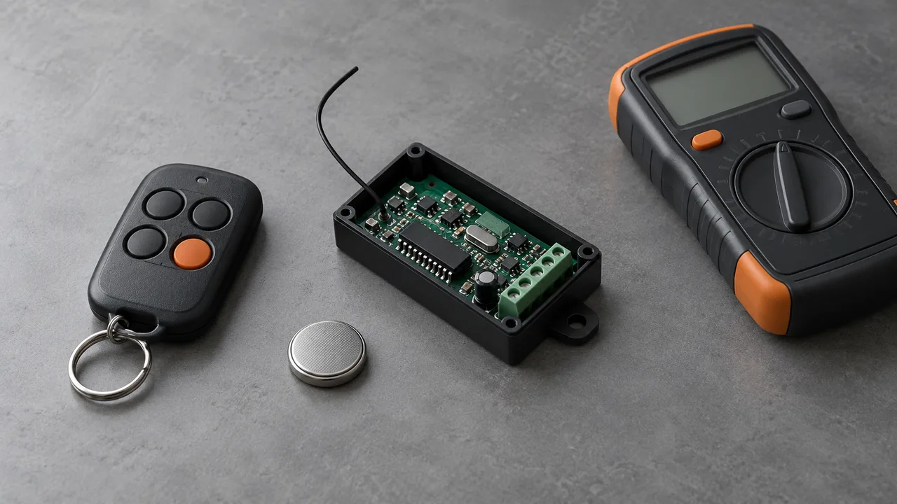
Identify the Failed Step
Start by separating enrollment from normal operation. Did the receiver confirm that it saved the remote, or are you assuming failure because the door did not move? A receiver may accept a command while the downstream controller is stopped by an input, interlock or output fault.
Record the remote model, receiver model, intended button action and exact indicator sequence. If an existing remote still operates the equipment, keep it as a reference. Change one thing at a time so the next result tells you something useful.
Check the Battery and Its Contacts
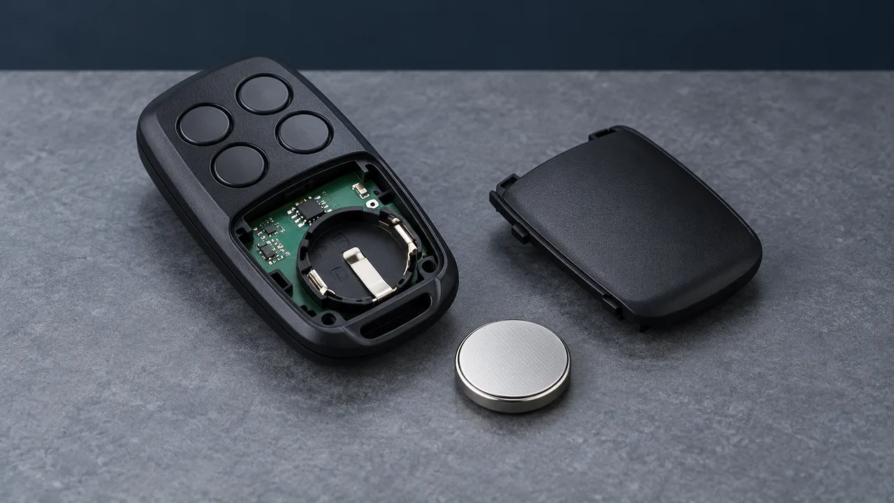
Intermittent operation, a sudden loss of range or a dim indicator are good reasons to check the battery first. Fit a fresh battery of the specified type and polarity. Inspect the holder for loose contacts, corrosion or a contact that no longer presses firmly against the cell.
A battery can show voltage at rest and still sag during a transmission pulse. A lit indicator does not establish that the supply stays within the radio circuit’s operating limits. If you measure voltage, compare the voltage during a button press with the limits for that remote; an unloaded reading alone is incomplete.
For the difference between remaining charge and voltage under load, see our CR2032 battery guide. Use the battery specified for your model; RF remotes do not all use a CR2032.
Confirm Frequency and Coding Compatibility
315 MHz and 433 MHz are familiar labels on RF remotes, but two identical housings can contain different radios. Check the exact operating frequency of both the remote and receiver against their labels, manuals or manufacturer’s model records. A housing or button count is not a reliable identifier.
Do not assume that every crystal or resonator is marked with the transmit frequency. Some radios synthesize the carrier from a lower-frequency reference. TI’s CC1101 data sheet, for example, describes a crystal reference and a programmable RF synthesizer. Board markings can be useful clues, but they need to be interpreted for that design.
Matching frequency is only one requirement. Modulation, coding protocol, button mapping and any rolling-code provisioning must also match. Learning describes how a receiver stores a transmitter; it does not by itself identify a separate security level or guarantee compatibility.
Microchip’s HCS301 documentation illustrates the extra state involved in one rolling-code system: transmitter identity, a key and synchronization information. A matching chip family or carrier frequency alone does not prove that a replacement has the correct configuration. See the replacement pairing guide for a fuller compatibility check.
Follow the Procedure for That Model
There is no universal pairing sequence. Some receivers have a learning button; others use a controller menu or a procedure involving an already authorized remote. Fixed-address systems may require matching settings rather than learning. Copying a signal into a remote is also different from enrolling it in the receiver.
- Use the instructions for the exact receiver and remote combination, including any required enrollment permission.
- Confirm the receiver’s documented learning-state indication before pressing the new remote.
- Use the specified button, hold time and learning window. A long press can select another function, including memory deletion.
- Use the documented distance and antenna arrangement. Start at a short practical distance without pressing the remote against the receiver antenna.
- Look for the model’s actual success indication, then test the intended button action in normal operation.
Avoid treating a flash or beep as a universal success signal. Nice’s SMXI/SMXIS instructions show distinct memorization modes and LED sequences. Those sequences are examples for the named receivers, not instructions for an unrelated product.
Compare Site and Bench Conditions
If the same pair works on the bench but fails after installation, compare antenna placement, metalwork, receiver supply and nearby equipment. Motor drives and switching supplies can introduce electrical noise; other transmitters using the same radio channel can interfere with reception. The actual effect depends on the equipment and installation.
Wi-Fi and Bluetooth normally operate in bands different from a 315 or 433 MHz remote. Their presence alone does not establish direct same-channel interference. Check the radio environment and possible supply or installation effects rather than blame every nearby wireless device.
Repeat the test with the same remote, receiver, battery and procedure, changing one condition at a time. Compare nearby equipment running and stopped where practical, and try the antenna placement permitted by the receiver instructions. Keep a note of what changed and whether the result repeats.
Separate the Remote, Receiver and Output
A flashing remote LED shows that its indicator circuit responded. It does not prove correct frequency, RF output, data timing or protocol. Likewise, a receiver entering learning mode shows that part of its control logic responded; it does not prove that its radio front end can recover the message.
- Compare an already enrolled, known-working remote on the same receiver. If it works, focus first on the new remote’s compatibility and enrollment.
- Where available, test the suspect remote with a known-compatible receiver using its documented procedure. Two unverified units are a poor reference pair.
- If the receiver cannot enter learning mode, check its documented supply requirements, programming restrictions and fault indications.
- If enrollment is confirmed but the equipment does not move, check button assignment, receiver output and the downstream controller’s status.
A frequency checker can indicate the presence of a signal within its capabilities, but that alone does not validate the encoded message. Where measurements are needed, record what the instrument actually established rather than label the whole remote “good.” Leave the controller’s required interlocks in operation during checks.
Check Capacity Before Clearing Memory
A full receiver memory can prevent a new enrollment, but a failed attempt does not prove the memory is full. Check the model’s capacity, how entries are counted and any full-memory indication. An entry may represent a whole transmitter or one button assignment.
Use individual deletion if the receiver supports it and the entry can be identified. Clear the whole memory only when the documented procedure calls for it and you have the information and access needed to enroll every remote that must keep working. A full reset may also change settings beyond the transmitter list.
Three Checks Worth Remembering
- A battery showing voltage at rest may still fail under transmission load.
- Matching frequency does not establish matching protocol or enrollment configuration.
- A remote LED or a receiver learning LED does not prove that the full control chain works.
Send a Useful Support Record
The practical lesson is to investigate in order: battery and contacts, radio compatibility, the exact learning sequence, installation conditions, receiver response and memory management. Hardware faults remain possible. The checklist helps produce evidence for the next decision rather than assign blame to the product or installer.
For a replacement-remote or receiver inquiry with Dongguan Fengxian Electronics Technology Co., Ltd., send the remote and receiver model numbers, their documented frequency, the button action you need and the steps already tried. Include the indicator sequence and whether an existing remote still works. Photos of labels and accessible boards can help identify the configuration.
Use the RF question form below to open an email draft. Review the message, attach your photos in your email app and send it. A clear test record makes the next compatibility or troubleshooting check more useful.

About the Author
Eric Huang
RF Remote Controls & Controllers Specialist
I work with trade buyers on custom RF remote and controller projects, automotive remote requests and aftermarket gate and garage remote sourcing. These guides help you define product requirements and plan sample checks before ordering.
Share your application or original system, target market and question to discuss the next steps.
Keep reading
Related articles
Why a Replacement Remote Will Not Pair
Separate failed enrollment from poor range, then check the receiver variant, code family, programming method and tested replacement model.
Read next TroubleshootingRF Remote Buttons Not Working: Check the Battery, Buttons and MCU
Trace a missed command from battery voltage under load through button contacts, MCU operation and the RF link before replacing parts.
Read next TroubleshootingDiagnose Short Range on a 433 MHz Remote
Use controlled substitutions and supply, antenna and decoding checks to find why a remote works at one installation but fails at another.
Read nextDiscuss Your Project or Replacement
Share your application or original system and your question to discuss the next step.
RF questions by email
Ask Eric About Your Remote or Receiver
Describe your remote or receiver, the issue and what you have already tried. Add model details and your country if available.
Opens a draft in your email app. Review it, attach any photos and send your message.