
Trace a missed command from battery voltage under load through button contacts, MCU operation and the RF link before replacing parts.
Reading mapArticle sections7 sections
You press the remote, and nothing happens. A weak battery, an intermittent battery contact, a worn button or a controller fault can all produce that symptom. So can a working transmitter whose command the receiver does not accept.
At Dongguan Fengxian Electronics Technology Co., Ltd., we approach this problem by following the power and signal path. Start with checks that are quick and informative, then move to board-level measurements when the earlier stages have been verified.
First record the symptom: one button or every button, intermittent operation or complete failure, close-range operation or no response at any distance. If a known-working, compatible remote already enrolled in the receiver is available, try it at the same location before opening the faulty unit.
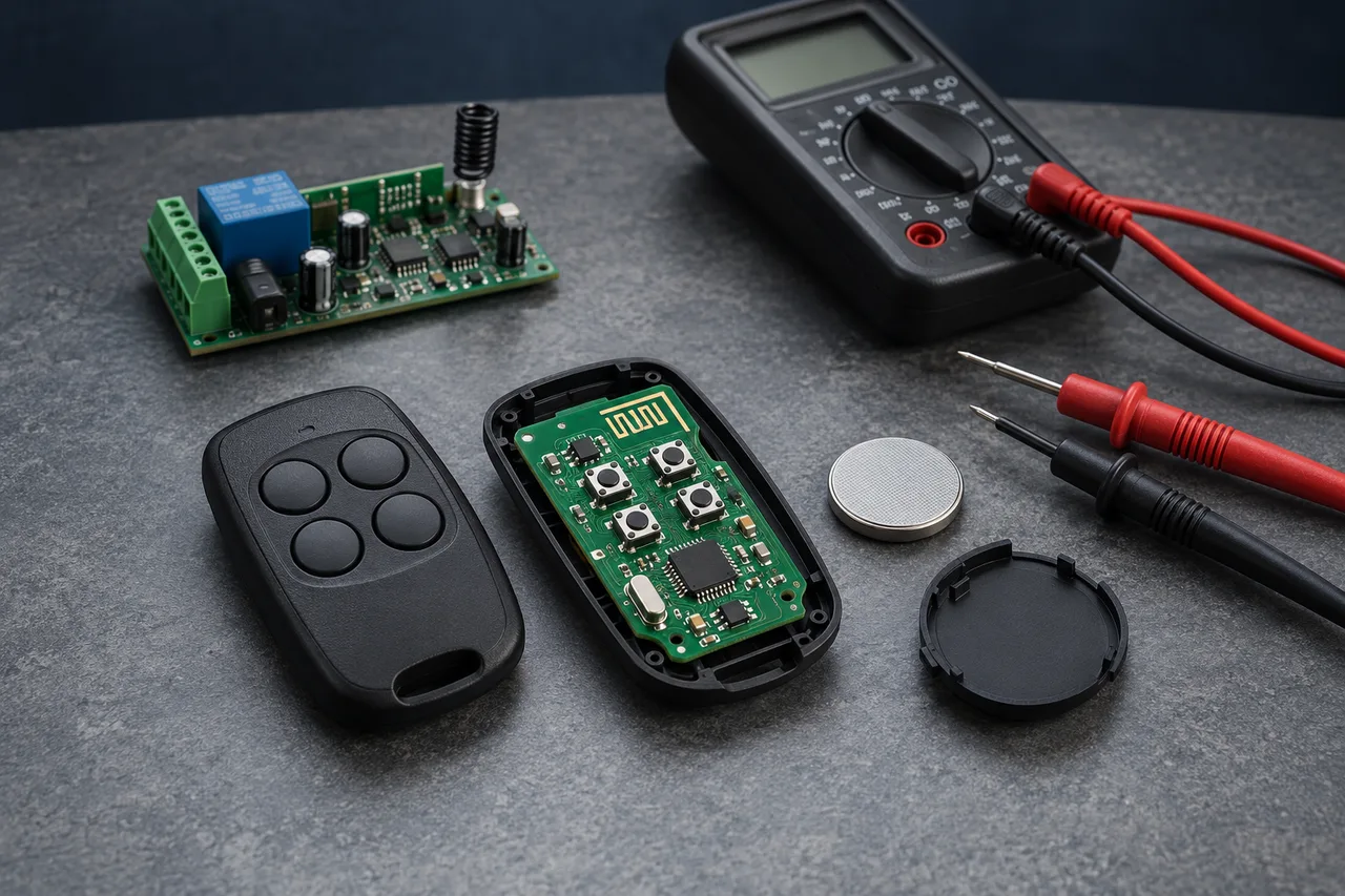
What Actually Happens When You Press a Button?
An RF remote turns a button press into a coded radio transmission. The battery supplies energy, the button changes an electrical input, and the MCU or dedicated encoder creates the command. The radio circuit and antenna transmit it; the receiver must receive, recognize and authorize it before issuing an output.
A fault anywhere along this path can look like a dead button. At each stage, ask two questions: is the required input present, and does the expected output follow? A tactile click is not proof of electrical contact; an LED flash is not proof of a valid radio command.
For bench troubleshooting, a useful default is battery → buttons → MCU → RF link and receiver. This is an order of verification cost, not a rule that prevents a quick receiver comparison first. Follow the evidence when a check identifies a different branch.
Start with the Battery and Its Contacts
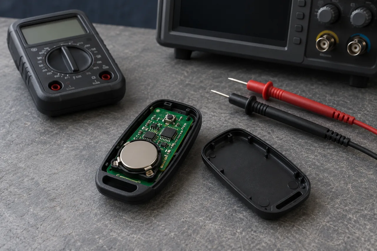
Fit a fresh battery of the specified type and confirm polarity. Inspect the holder for loose or deformed spring contacts, oxidation and leakage. A connection that changes when the case is squeezed can explain intermittent operation even when the cell itself is good.
Measure idle voltage, but do not use it as the final verdict. Panasonic's CR2032 datasheet specifies a nominal 3 V cell and a 0.2 mA continuous drain, with discharge curves using a 2.0 V cutoff. That cutoff describes the battery test; it is not a universal remote-control replacement threshold.
The useful measurement is voltage during an actual transmission. An aged cell can show an acceptable idle voltage and then sag under a pulse load. Battery contact resistance adds another voltage drop. Either can bring the controller or radio below its operating limit.
With the battery installed, measure across its terminals while pressing a button and compare the result with idle voltage. Also measure at the controller supply pins: a stable cell voltage with a falling board supply points toward the holder, connections or power path. Some remotes send a short burst rather than transmitting continuously while a key is held.
A multimeter can miss a brief voltage dip. If the symptom suggests resets during transmission, use an oscilloscope with an appropriate probe connection and capture the supply minimum during the burst. Compare it with the controller and radio operating limits and any brownout setting.
Cold conditions can reduce the available voltage margin under load. Use the exact cell manufacturer's temperature and pulse-discharge data rather than treating every CR2032 as identical. A rated temperature range alone does not guarantee that a particular remote will transmit reliably at its lower limit.
For a deeper explanation of charge budget versus pulse voltage, see our CR2032 battery-life guide. If a fresh cell restores operation, repeat the test with the case assembled and check that the contacts remain stable. If the fault persists, move to the button input.
Verify the Button Electrically
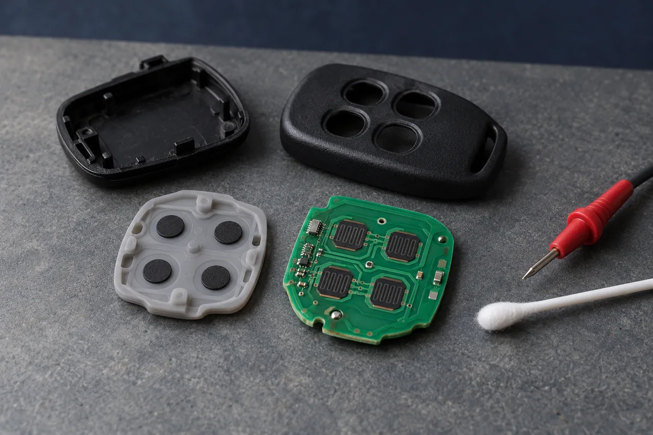
A button is an electrical switch as well as a mechanical part. Pressing it must produce an input level that the controller recognizes. Many designs pull an input to ground against a pull-up resistor; others use a key matrix, pull-downs or a resistor ladder. Check the actual circuit before interpreting a measurement.
- Check for a sticking keycap, poor return, misalignment or a damaged actuator.
- On silicone keypads, inspect conductive pills and PCB contact pads for wear, contamination or damage.
- On tactile switches, check the switch contacts, solder joints and surrounding traces.
- Look for moisture residue, cracked tracks and a shared connection that could affect several keys.
Remove the battery before measuring resistance. On an isolated, normally open switch, the released state should be open and the pressed state should show a stable contact resistance within the part specification. In-circuit measurements may include parallel paths or semiconductor junctions; isolate the component if the result is ambiguous.
Do not use a single resistance threshold for every button. Carbon-pill contacts and metal-contact switches have different specifications. Whether the controller recognizes a press depends on contact resistance, pull-up or pull-down resistance, input thresholds and the scanning method.
If the contact test passes, restore power and verify the input change at the MCU using the schematic and device datasheet. A switch can close correctly while a broken trace prevents the input from changing. For scanned keys, a multimeter may average the signal; a scope can show what happens during the scan.
One failed key points first to that button, its trace or its assigned function. All keys failing points toward shared circuitry, but does not prove an MCU fault: a broken common keypad connection, a stuck key or a scanning problem can also affect the whole keypad.
Clean only with a method approved for the keypad and PCB materials. Do not assume alcohol is suitable for every conductive coating, adhesive or printed legend. Avoid abrasive rubbing of carbon pads. Replace a worn keypad or switch assembly when cleaning cannot restore a stable contact.
Check MCU Operation Before Blaming the Chip
Once the power path and button input are verified, check the controller. It needs a valid supply, correct reset behavior, a working clock and executing firmware. Dedicated encoders and integrated radio controllers may combine these functions differently; use the actual device documentation.
- Supply: measure at the controller pins during wake-up and transmission; inspect the power path and decoupling components.
- Reset: look for repeated restarts or a reset input held active, where that input is exposed.
- Clock: check the oscillator arrangement, assembly and configuration; an external crystal is not required by every design.
- Execution: use a documented debug interface, diagnostic output or command-data signal to confirm that the detected press reaches the transmission routine.
Take care when checking a crystal oscillator. Probe capacitance can change its frequency or stop it oscillating. Texas Instruments' oscillator guide explains this measurement effect; a buffered clock output or a suitable low-capacitance probe is preferable when the design provides that option.
An LED flash is a clue, not a pass certificate. Depending on the circuit, it may show that a button path or some firmware is active. It does not establish RF output, the correct code or receiver acceptance. An unlit LED can also be a failed LED or driver, and some remotes have no indicator at all.
The Si4010 datasheet is one example of a remote-control device with an MCU, radio, LED driver and button wake-up functions in one chip. Its arrangement illustrates why a visible indicator and a successful RF command must still be verified separately; it does not identify the chip inside an unknown remote.
ESD damage is a possible cause of an abnormal input or excessive current, but those symptoms are not unique to ESD. Check for contamination, shorts and damaged peripheral components before concluding that the MCU must be replaced.
If the same failure is reproducible across units with verified hardware, investigate wake-up handling, debounce, key scanning and the transmit sequence. Record the firmware revision and a repeatable trigger rather than diagnosing firmware from the absence of a response alone.
Separate the RF Link from Receiver Acceptance
A controller can execute a command while the radio fails to transmit it. Conversely, a transmitter can emit a signal that the receiver hears but rejects. Check frequency, modulation, protocol and enrollment as separate requirements.
- Transmitter: inspect the radio circuit, oscillator or frequency-setting parts, matching components, antenna and solder joints; compare RF output with a known-good unit where suitable equipment is available.
- Receiver: check its supply, antenna and response to an already enrolled compatible transmitter.
- Code acceptance: verify the supported code family, transmitter identity, button assignment and documented enrollment or synchronization procedure.
- Environment: repeat at a controlled distance and orientation; consider metal obstruction and interference on the operating channel.
- Equipment: if the receiver accepts the command or switches its output but the load does not move, investigate the downstream control, interlocks and actuator.
Use an already enrolled, known-working compatible remote at the same receiver and location. If it works and the suspect remote does not, focus on the suspect transmitter and its registration or assigned function. If both fail, examine common conditions such as receiver power, interference and the connected equipment. Neither result alone identifies a specific failed component.
Rolling-code synchronization and transmitter enrollment are different operations. Microchip's HCS301 documentation describes an example of receiver synchronization windows and sequential transmissions for resynchronization. The exact behavior depends on the receiver implementation; follow its instructions rather than assuming that re-pairing will recover lost credentials or repair corrupt transmitter memory.
If operation is possible only at short range, use the short-range diagnostic guide. If transmission appears normal but enrollment fails, use the replacement-remote pairing guide. Operating bands and power limits depend on the destination market and device category; a troubleshooting article cannot supply a universal legal frequency or power setting.
A Quick Troubleshooting Checklist
- 1. Record whether the fault affects one key, all keys, range or intermittent operation. Try an already enrolled, known-working compatible remote if available.
- 2. Fit a fresh battery of the specified type and inspect polarity, holder contacts and the power path.
- 3. Measure voltage during transmission at the battery and controller supply; use a scope if a brief dip is suspected.
- 4. With power removed, check button contacts. With power restored, verify the expected controller input change.
- 5. Treat LED behavior as a clue. Verify controller supply, reset, clock and command execution where accessible.
- 6. Check RF output, receiver acceptance and the documented enrollment or synchronization procedure.
- 7. If the receiver output operates, follow the fault into the connected equipment. After a repair, retest every key with the case assembled.
Keep a short fault record: remote and receiver models, battery type, affected buttons, idle and minimum loaded voltage, test distance and the comparison result. These details make a supplier discussion more useful than simply reporting that the remote does not work.
Reliability Starts in the Design
Troubleshooting addresses a failure after it occurs. Design verification should give the battery and power path enough margin for temperature, aging and transmission pulses; match the button assembly to its use; and validate controller wake-up, reset, decoupling and ESD protection.
Test the complete remote with its housing, battery and intended receiver. Check each button and repeated operation under the agreed conditions. Component specifications guide that work, but do not replace finished-product verification.
At Dongguan Fengxian Electronics Technology Co., Ltd., this is the approach we use for remote-control development and troubleshooting: return to the required input and output at each stage, then locate the break in the chain. If you are investigating a similar fault, use the RF question form below and include the models and measurements you have checked.
The component examples and values above are general references. Use the datasheets for the actual battery, switch, controller and radio, together with the receiver instructions and complete-product test results, to set the limits for your design.

About the Author
Eric Huang
RF Remote Controls & Controllers Specialist
I work with trade buyers on custom RF remote and controller projects, automotive remote requests and aftermarket gate and garage remote sourcing. These guides help you define product requirements and plan sample checks before ordering.
Share your application or original system, target market and question to discuss the next steps.
Keep reading
Related articles
How Can One CR2032 Keep an RF Remote Working for Years?
Follow the microamp budget, the transmit pulse and the small design details that determine whether a coin-cell remote still responds years later.
Read next TroubleshootingDiagnose Short Range on a 433 MHz Remote
Use controlled substitutions and supply, antenna and decoding checks to find why a remote works at one installation but fails at another.
Read next CompatibilityWhy a Replacement Remote Will Not Pair
Separate failed enrollment from poor range, then check the receiver variant, code family, programming method and tested replacement model.
Read nextDiscuss Your Project or Replacement
Share your application or original system and your question to discuss the next step.
RF questions by email
Ask Eric About Your Remote or Receiver
Describe your remote or receiver, the issue and what you have already tried. Add model details and your country if available.
Opens a draft in your email app. Review it, attach any photos and send your message.