
Use controlled substitutions and supply, antenna and decoding checks to find why a remote works at one installation but fails at another.
Reading mapArticle sections8 sections
Two installations using the same remote can have very different usable range. That does not identify a bad batch by itself: the receivers, antennas, supplies and radio paths may differ.
When one gate responds at distance and another needs a close approach, swap the remotes before deciding which part is at fault.
A useful diagnosis follows the command from transmitter supply through the radio path to receiver decoding. Keep the test location and procedure fixed while changing one part.
Start with a Controlled Comparison
Test a known-good remote at both receivers, then test the suspect remote at the same locations. A failure that follows the remote points toward the transmitter; one that stays at the site points toward the receiver or installation.
Next check supply voltage during a press, the receiver antenna arrangement and equipment operating nearby. These checks are accessible and can isolate several different causes.
If those checks do not explain the result, measure transmitter output and frequency, receiver sensitivity and interference rejection. Do not infer any of these from a frequency label or a short-range response.
An Indicator LED Is Not a Battery Test
A lit LED shows that its circuit receives enough voltage to emit light. It does not show that the radio output is correct or that the transmitter completes a valid command.
Use the battery type specified for the remote. Some use an A23 battery; others use a coin cell. Their nominal voltages do not provide a universal minimum operating threshold.
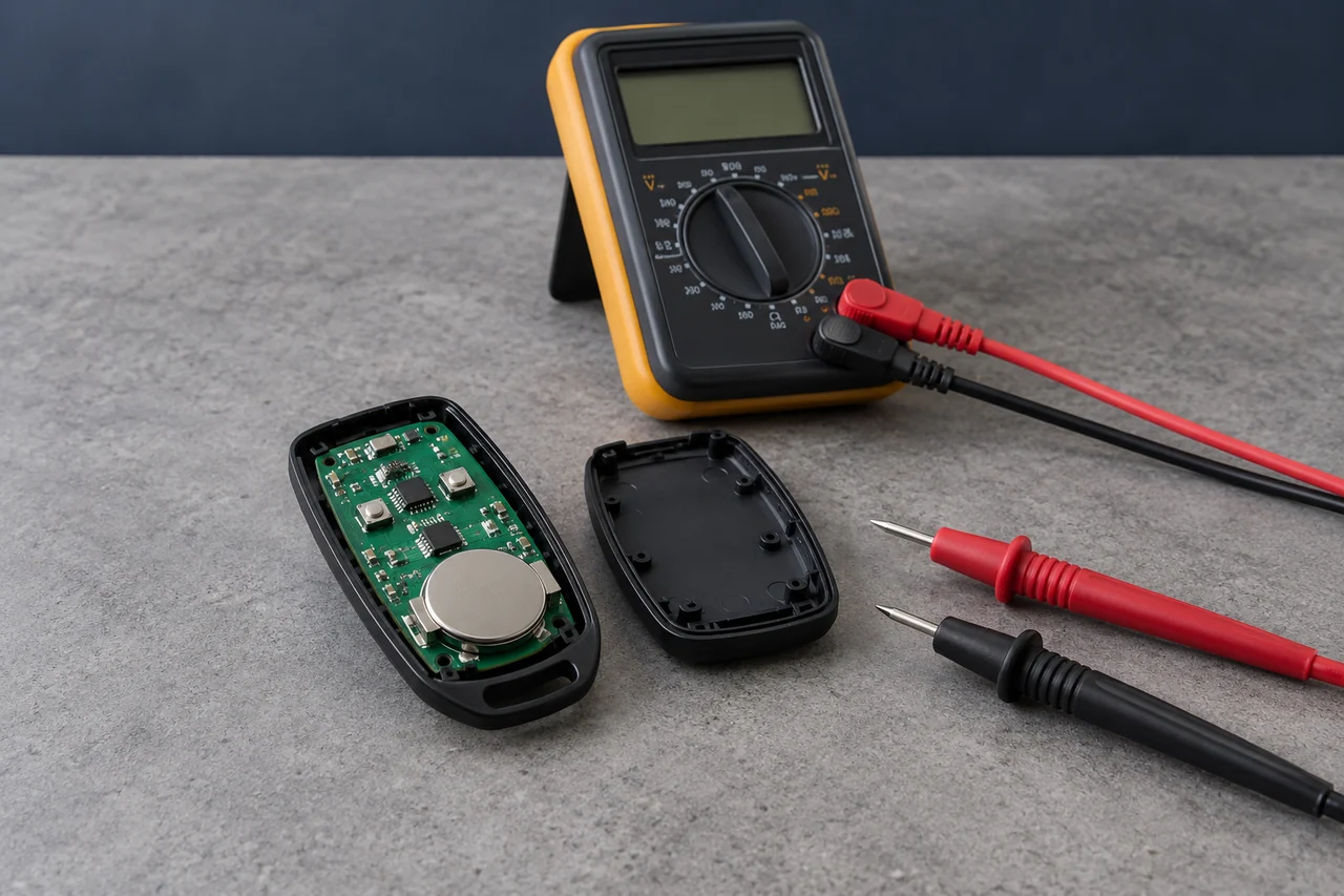
Measure at the transmitter supply during a button press and compare the minimum with the circuit’s operating requirements. For short dips, an oscilloscope or suitable capture instrument is more useful than a slowly updating meter.
Inspect the contacts as well. A loose or corroded connection can add voltage drop even when the cell’s open-circuit voltage looks normal.
On a new design, examine supply decoupling, current demand and reset behavior. A supply dip may reduce RF output, reset the controller or corrupt timing; the observed failure depends on the circuit.
- Replace the cell with a known-good one of the specified type and repeat the fixed-location test.
- Measure the lowest supply voltage during transmission rather than only resting voltage.
- If measuring current, account for the meter or shunt’s added voltage drop.
- For coin cells, check the pulse voltage against the radio and MCU requirements, including late-life and cold conditions.
Check the Antenna in Its Installed Position
A wire squeezed against a metal cabinet can behave differently from the same antenna clear of it. Follow the receiver’s approved mounting and antenna instructions before making changes.
A free-space quarter-wave wire at 433.92 MHz starts around 17.3 cm. Ground plane, enclosure and nearby objects alter the installed antenna. A deliberately designed helix or PCB antenna should not be straightened or extended by guesswork.
Where the receiver supports it, compare the specified external antenna in a clear position with the original installation. Record the result; no fixed distance gain follows from moving it outside a cabinet.
- Check antenna type, connection, damage and any prescribed ground or mounting arrangement.
- Keep a simple wire antenna in the shape specified by the manufacturer.
- Compare orientations while preserving the same test path; polarization can affect received signal.
- Use a supported external antenna if the radio is inside a metal cabinet, and include feedline loss.
- Repeat the range test with the cabinet and gate in their normal open and closed states.
Separate Interference from Path Loss
A 433 MHz receiver may encounter other transmitters or unintended emissions. Local spectrum use is market-dependent; describing 315 MHz and 433 MHz as universally available shared bands is too broad.
Supplies, LED drivers or motor electronics are possible noise sources, but their presence is not proof. Their emissions must reach the receive path or supply strongly enough to affect this particular receiver.
Interference may overlap the desired channel or overload the receiver from another frequency. Receiver selectivity and blocking specifications describe different parts of this problem.
If the fault appears only at certain times, log which equipment changes state. With safe access to that equipment, perform an on/off comparison and restore the original condition to confirm the relationship.
- Turn suspect nonessential equipment off one at a time and repeat the fixed-location test.
- Try an approved clean receiver supply to separate supply-borne noise from radio-path effects.
- Move the receiver or supported antenna away from the suspected source and compare results.
- If selecting another receiver, compare sensitivity, adjacent-channel rejection and blocking under the intended signal; architecture names alone do not establish performance.
A Received Frame Can Still Be Rejected
Coding does not change free-space propagation. It changes which received bit patterns the decoder accepts and how repeated commands are handled.
For example, the HCS301 sends a 66-bit code word plus transmission framing. Airtime depends on baud rate and framing; a rolling-code receiver also checks authentication and synchronization.
A longer frame has more opportunities for bit errors when other conditions are fixed. That does not make fixed code inherently longer-range: modulation, error checks, repetition and the receiver all affect command success.
A remote that transmits but is not registered, uses incompatible timing or falls outside a rolling-code synchronization window can fail even nearby. Follow the receiver’s documented diagnosis and enrollment procedure.
- Confirm exact frequency, modulation and code family, not only a 433 MHz label.
- Separate missing RF reception from a decoded command that the controller rejects.
- Check registration and synchronization using the receiver’s manual.
- Compare sensitivity figures only at matching waveform, data rate, bandwidth and error target.
Check Power Changes Against the Product’s Rules
Increasing transmit power may improve a weak-signal link, but it cannot correct wrong coding or guarantee operation through interference.
Radio limits depend on the country, equipment category and measurement method. Conducted power at the chip is not the same as ERP, EIRP or radiated field strength with the product antenna.
The EU SRD decision sets conditional frequency entries; US periodic control transmitters have conditions under 47 CFR §15.231. Use the requirements and authorization for the actual product and destination rather than borrowing a power limit from another market.
First recover avoidable losses: poor contacts, unsupported antenna placement and noisy receiver power. A hardware or power modification should then be evaluated for both radio performance and compliance.
A Gateway Needs Its Own Evidence
A gateway can add a separate remote-control path when the local handheld link does not cover every use case. It is an architecture change, not proof that the original RF fault is resolved.
A phone command or a radio acknowledgment does not confirm that a gate closed. Position feedback requires a suitable sensor or documented status interface, and control remains subject to the gate operator’s safety functions.
If a gateway is part of the project, test local operation with internet service unavailable and define how the user can confirm the actual gate state.
Keep local range and remote access as separate acceptance items. Otherwise a working app can conceal a handheld link that still fails at the required approach point.
What to Record for Technical Support
- Transmitter: model, revision, battery type, contact condition and lowest voltage during a press.
- Receiver: model, supply, antenna, mounting and any external cable.
- Compatibility: exact frequency, modulation, protocol and registration status.
- Path: distance, remote orientation, vehicle position and door/cabinet state.
- Interference: equipment on/off comparisons and time-dependent symptoms.
- Results: attempt counts and whether the failure follows a swapped remote or stays at one installation.
Send these facts with the symptom. “Works at one gate, fails at another” is a starting point; the controlled comparison identifies where the next measurement belongs.
If the cause remains uncertain, keep the original configuration available for reproduction. Replacing several parts can restore operation while leaving the underlying fault unexplained.

About the Author
Eric Huang
RF Remote Controls & Controllers Specialist
I work with trade buyers on custom RF remote and controller projects, automotive remote requests and aftermarket gate and garage remote sourcing. These guides help you define product requirements and plan sample checks before ordering.
Share your application or original system, target market and question to discuss the next steps.
Keep reading
Related articles
Receiver Sensitivity: Compare the Test Conditions
Read a sensitivity figure with its waveform, bandwidth and error target, then test whether receiver performance is limiting the installed link.
Read next RF EngineeringHow Can One CR2032 Keep an RF Remote Working for Years?
Follow the microamp budget, the transmit pulse and the small design details that determine whether a coin-cell remote still responds years later.
Read next TroubleshootingWhy a Copy Remote Reports Success but Does Not Work
Separate signal learning, receiver enrollment and range problems before choosing a copy remote, a dedicated replacement or an assessed receiver upgrade.
Read nextDiscuss Your Project or Replacement
Share your application or original system and your question to discuss the next step.
RF questions by email
Ask Eric About Your Remote or Receiver
Describe your remote or receiver, the issue and what you have already tried. Add model details and your country if available.
Opens a draft in your email app. Review it, attach any photos and send your message.