
Follow the microamp budget, the transmit pulse and the small design details that determine whether a coin-cell remote still responds years later.
Reading mapArticle sections12 sections
While reviewing low-power RF design notes, I started with a deceptively simple question: how can one CR2032 keep a small garage-door remote working for years? And why might another design begin missing commands much sooner?
It is tempting to put the whole difference down to the battery. Cell quality matters, but that answer leaves out the circuit that spends the charge: the standby load, the radio burst, the LED and everything the firmware forgets to turn off.
Think of the coin cell as an account with a useful balance and a limited ability to make a large withdrawal at once. A low average current can stretch the balance. A demanding transmit pulse can still pull the voltage below what the electronics need.
That gives us two questions to answer separately: how much charge does the complete remote use over time, and can the battery deliver each command without a damaging voltage dip? Years of service require both.
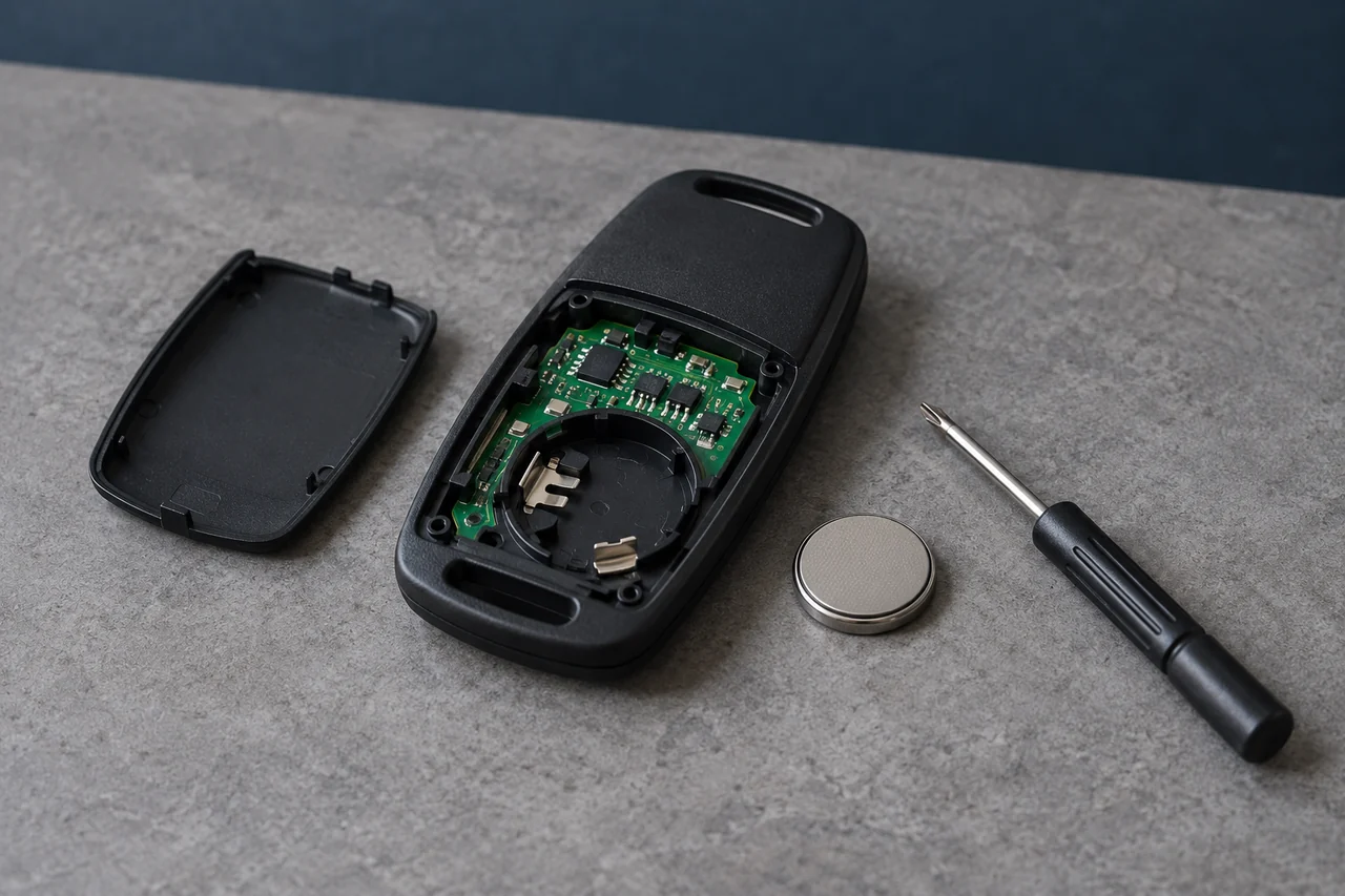
Read the Capacity with Its Test Load
CR2032 is a cell size and chemistry designation, not a promise of one fixed capacity under every load. Supplier ratings use specified conditions.
A remote imposes a different load: long idle periods interrupted by encoding, radio transmission and LED indication. The cell must support that profile above the circuit’s operating threshold.
Panasonic’s CR2032 datasheet lists 3 V nominal voltage, 225 mAh nominal capacity and 0.2 mA continuous drain. The continuous-drain entry is a reference condition, not a maximum permitted pulse current.
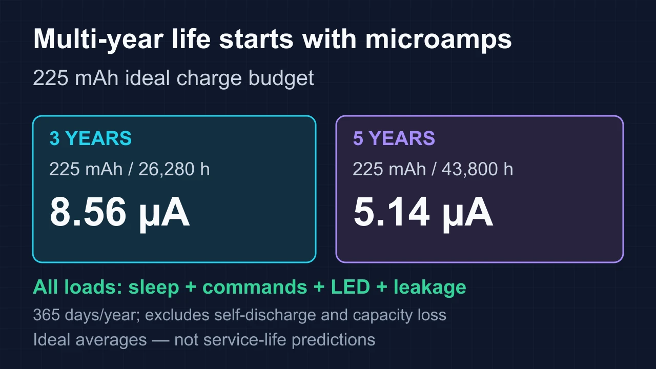
Using 225 mAh as an ideal charge budget shows how small the average current must be for multi-year operation. It does not establish that all 225 mAh will be available at the remote’s cutoff voltage.
- Three years at 365 days/year is 26,280 hours; 225 mAh / 26,280 h ≈ 0.00856 mA = 8.56 µA.
- Five years is 43,800 hours; the same calculation gives about 5.14 µA.
- These ideal averages include every electrical load, but omit self-discharge and any loss of usable capacity under the real load and cutoff.
This is where the design becomes unforgiving. An extra 1 µA running continuously uses 8.76 mAh in a 365-day year. A small leakage path is small on the bench, but it keeps collecting charge every hour the remote sits unused.
Measure standby current at the battery terminals after the product has settled into its normal idle state. A low MCU sleep figure excludes the regulator, radio, LED paths and board leakage.
- GPIO bias: check for enabled pull resistors that conduct continuously through a switch or external circuit.
- Debug and peripherals: confirm the production firmware enters the intended low-power mode.
- LED: integrate its current over the actual indication time, including a long press.
- Buttons: look for repeated wake-ups, stuck-key behavior or firmware that remains active after release.
Turn Usage into a Charge Budget
Ask for a defined life estimate: cell model, operating temperature, idle current, presses per day, command duration and end-of-life criterion. A calendar-life number without those assumptions is incomplete.
“How long will it last?” deserves a clear answer, but a single number hides the usage model. A remote used a few times a day and one carried with a button held down in a bag are drawing from very different accounts. State the conditions before offering the estimate.
For a daily estimate, Qday = 24 × Isleep + N × Σ[(Ij − Isleep) × tj] / 3600. Use current in mA, each active-state duration tj in seconds, and N commands per day; the result is mAh/day. Subtracting Isleep avoids counting the same time twice.
As a hypothetical example, 15 mA for 0.2 s is 0.000833 mAh per command before other active loads. At 20 commands/day that is about 6.08 mAh/year. A continuous 2 µA idle load adds 17.52 mAh/year. These are arithmetic inputs, not measured remote performance.
Check Voltage During the Pulse
Energizer’s CR2032 datasheet rates 235 mAh typical at 21°C through 15 kΩ to 2.0 V. Its separate pulse curve uses 2-second, 400 Ω pulses 12 times/day on top of a continuous 15 kΩ background load. That is not a universal RF-remote load profile.
An idle voltage measurement leaves out the most demanding interval. Capture voltage at the radio and MCU during wake-up, transmit and any repeated command sequence.
Record the total current waveform rather than assuming a typical transmitter current. MCU startup, LEDs and other loads can overlap with the radio burst.
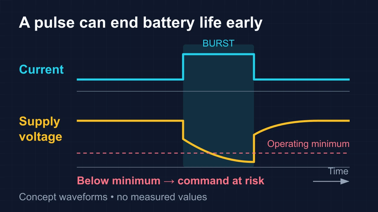
The Nordic Semiconductor/Energizer pulse-load study explains why usable capacity depends on pulse magnitude, duration, recovery time and the circuit’s functional cutoff. A burst can cross that cutoff before the cell has exhausted all its charge.
Battery life ends when the product cannot meet its operating requirement, even if the cell retains charge.
A first approximation to the immediate voltage drop is I × effective series resistance. Longer pulses also involve electrochemical polarization, so one fixed resistor does not fully model the cell.
If the voltage falls below the MCU or RF requirements, the command may reset, lose timing or transmit incorrectly. A range complaint can therefore be a power-integrity symptom.
Test new and partly discharged cells, cold conditions within the product rating, rapid presses and a held button. A new cell at room temperature is only one operating condition.
Shorten Active Time without Breaking the Command
Sleep quietly. Wake promptly. Complete the command. Go straight back to sleep.
Measure wake-up, oscillator startup, encoding, RF activity, indication and return to sleep. The longest interval is not necessarily the largest contributor to charge.
- Standby: turn off unused blocks while keeping the intended wake source available.
- Active period: finish the required frame and necessary repetitions before shutting down.
- Return to idle: verify that no timer, peripheral or held-button path keeps the system awake unintentionally.
Use Chip Specs as Inputs, Not Product Guarantees
The Si4010-C2 datasheet lists 10 nA typical standby with all GPIO floating or held high, at its stated DC test conditions. Its timer-only mode is 700 nA typical. These are distinct modes; neither value is a guarantee for an assembled remote.
Choose the radio architecture for compatibility, current, wake-up time and supply range. Integration can simplify the circuit, but remaining external leakage and firmware behavior still need measurement.
A low-power design still needs enough RF output to complete its job. Microchip’s RF Basics Design Guide describes the MICRF112, a 300–450 MHz ASK/FSK transmitter capable of +10 dBm output and operation down to 1.8 V. Those capabilities do not establish the current of your finished remote or its permitted output in a destination market.
Configure GPIO for the Selected Device
ST’s AN4899 explains that STM32 analog mode disables the digital input buffer. For unused pins, follow that device’s low-power guidance; for digital wake inputs, maintain a defined level. Do not apply one blanket “pull every pin high or low” rule to all modes and chips.
A pull resistor can itself spend the idle budget when a switch or another device holds the opposite level. Check current paths, external pin voltages and back-powering, not just the register setting.
The unglamorous checks matter here: debug interfaces, enabled clocks, regulator quiescent current and peripherals that remain powered. More integration can remove some paths, but an additional component only costs standby current if the circuit gives it a path to draw it.
Check Wake-Up and Held-Button Behavior
A button interrupt can avoid repeated polling, but it still needs an appropriate bias circuit and a wake mode supported by the MCU. Compare the complete current profile rather than assuming interrupts always use less energy.
Mechanical bounce can generate multiple edges. Debounce and command handling should produce the intended behavior, including after a long hold or noisy contact, without repeatedly restarting transmission.
Include RF Repetition in the Budget
Higher output settings, longer airtime and additional repeats can consume more charge per press. The actual increase depends on the radio, supply and firmware, and must be measured.
Reducing repetitions indiscriminately can lower command success. Keep the receiver’s required timing and protocol; choose the repeat count from measured success and latency rather than battery arithmetic alone.
For one-way remotes, repeated frames are usually sent without confirmation. ACK-based retries require a receiver in the handheld and a return link; they cannot be added to a transmitter-only design by a firmware label.
Account for the LED
Measure LED current and on-time. Its average contribution is small only if its total charge per command is small relative to the rest of the profile.
For illustration, 2 mA for 300 ms costs 0.000167 mAh; reducing that to 30 ms cuts this particular contribution tenfold. Check that the shorter indication remains useful and that the firmware implements the intended timing.
There is no universal 30 ms rule. The light needs to be visible in the intended conditions, and it must not imply that the door moved when it only indicates local transmission. Spend enough charge to give useful feedback, then turn it off.
Check the Hardware and Firmware Together
A reservoir capacitor may reduce a short pulse’s voltage dip, but sizing depends on pulse charge, allowed droop and the cell’s recharge path. Capacitor leakage and ESR also matter at microamp standby levels.
Do not use an ideal capacitance calculation as evidence of service life. Verify the supply waveform with the real cell, capacitor, layout and repeated-command pattern.
- Cell: select the documented chemistry, supplier and capacity test conditions.
- Current: measure total standby and charge per complete command.
- GPIO: inspect bias, external drive and low-power settings for the actual MCU.
- Firmware: test bounce, long hold, repeated commands and return to sleep.
- Radio: retain required framing, repetitions and applicable duty conditions.
- LED and peripherals: include their currents and timings.
- Power integrity: check burst voltage at MCU and radio pins with relevant cells and temperatures.
- Board: investigate contamination, unintended leakage and battery-contact resistance.
- End point: define the minimum voltage and required command performance for replacement.
Retain the waveform and assumptions with the life estimate. A supplier can then explain whether a shorter interval comes from changed usage, standby leakage or pulse-voltage failure.
Define When the Battery Needs Replacing
Choose an end point tied to actual operation: supply minimum, command-success requirement or a documented low-battery indication. The battery datasheet’s cutoff may differ from the product’s.
If a low-battery warning is included, test it with a realistic pulse load. An unloaded voltage threshold can miss a cell that collapses during transmission.
Verify both the final command and the warning behavior near that end point, including after recovery from several presses.
A calendar estimate should state its assumptions and uncertainty. It should not imply that all users, cell lots and temperatures produce the same replacement interval.
For buyers, the strongest answer is a measured profile, a defined usage model and evidence that the burst voltage remains adequate over the planned service interval.
That brings us back to the little remote waiting on a key ring. The user does not see the GPIO settings, the current trace or the careful return to sleep. They press the button and expect a response. Low-power engineering earns that trust in all the quiet hours between commands.
Primary Documents Used Here
- Panasonic CR2032: nominal capacity and continuous reference drain.
- Energizer CR2032: capacity conditions and a specified background-plus-pulse curve.
- Nordic Semiconductor/Energizer study: pulse-voltage effects and functional cutoff.
- Silicon Labs Si4010-C2: mode-specific typical currents and GPIO conditions.
- STMicroelectronics AN4899: device-specific GPIO and low-power configuration.
- Microchip RF Basics Design Guide: transmitter architecture, output and supply range.

About the Author
Eric Huang
RF Remote Controls & Controllers Specialist
I work with trade buyers on custom RF remote and controller projects, automotive remote requests and aftermarket gate and garage remote sourcing. These guides help you define product requirements and plan sample checks before ordering.
Share your application or original system, target market and question to discuss the next steps.
Keep reading
Related articles
RF Transmitter Modules: Check Output and Repeatability
Compare carrier accuracy, matching, unwanted emissions and sample variation under the conditions the finished remote must meet.
Read next RF EngineeringRF Remote Collisions: Check the Hardware and Protocol
Separate one-way repetition from receive-capable channel sensing and two-way acknowledgments, then test command overlap and duplicate handling.
Read next TroubleshootingWhy a Copy Remote Reports Success but Does Not Work
Separate signal learning, receiver enrollment and range problems before choosing a copy remote, a dedicated replacement or an assessed receiver upgrade.
Read nextDiscuss Your Project or Replacement
Share your application or original system and your question to discuss the next step.
RF questions by email
Ask Eric About Your Remote or Receiver
Describe your remote or receiver, the issue and what you have already tried. Add model details and your country if available.
Opens a draft in your email app. Review it, attach any photos and send your message.