
Read a sensitivity figure with its waveform, bandwidth and error target, then test whether receiver performance is limiting the installed link.
Reading mapArticle sections7 sections
A receiver sensitivity number is useful when two RF systems have different range. It is also easy to misuse: the number describes a specified waveform and error target, not a distance the finished product must reach.
If a command works nearby and fails farther away, compare the desired signal at the receiver with the threshold needed for reliable decoding. Supply faults, antenna losses and interference can all change that comparison.
Before buying a replacement receiver, ask how its sensitivity was measured and whether those settings match your transmitter. A better-looking dBm value may describe a much slower link.
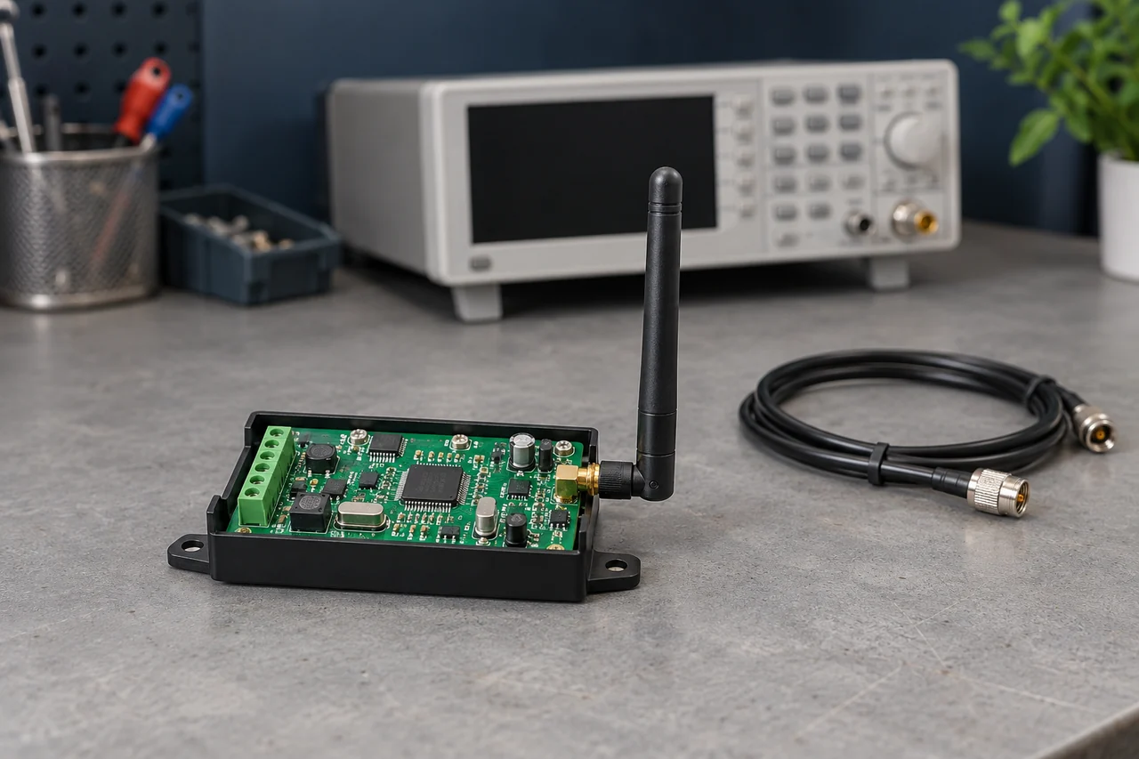
Sensitivity Measures a Receive Threshold
A sensitivity test applies a known RF waveform at progressively lower input power. The threshold is the level where a stated error criterion is reached.
That criterion might be bit error rate, BER, or packet error rate, PER. They are not interchangeable: a packet contains many bits and may be rejected if any required bit is wrong.
The measured point is usually a defined conducted RF input. It excludes some losses in the product antenna and installed path, unless the specification explicitly uses a radiated test.
Receiver sensitivity therefore answers a narrow question: how weak can this waveform be at this input while meeting this error target? It does not answer how well the receiver tolerates another transmitter nearby.
Read dBm as a Power Level
dBm expresses power relative to 1 mW: P(dBm) = 10 log10[P(mW)]. A negative value is a small positive power, not negative energy.
Under the same conditions, a more negative threshold means the receiver can meet the criterion with less input power. It does not automatically mean better interference rejection.
For example, thresholds of -105 dBm and -90 dBm differ by 15 dB. Treat those as hypothetical, comparable specifications rather than claims about generic receiver classes.
The power ratio is 10^(15/10), approximately 31.6. A 15 dB improvement means the same receive criterion can be met with about one-thirty-second of the input power.
The CC1101 datasheet shows why the test conditions matter: its 433 MHz -116 dBm figure uses 0.6 kBaud GFSK, 20-byte packets, 1% PER, 14.3 kHz deviation and a 58 kHz channel filter.
That number cannot be carried over to an arbitrary ASK gate remote or faster CC1101 setting. Check whether a quoted value is typical or guaranteed and how it changes across the rated supply and temperature range.
Use Free-Space Loss as a Model
The ITU free-space model gives about 6 dB more path loss when distance doubles, with frequency and antenna gains unchanged.
This model assumes a free-space path. A real gate installation includes ground reflection, obstructions and changing orientation, so received power may rise or fall irregularly as the user moves.
For illustration only, assume -75 dBm at 50 m and ideal free-space scaling. The calculated levels, not measured product results, would be:
- 50 m: -75 dBm, assumed starting value.
- 100 m: about -81 dBm.
- 200 m: about -87 dBm.
- 400 m: about -93 dBm.
- 800 m: about -99 dBm.
At the calculated -87 dBm point, a -90 dBm threshold leaves only 3 dB of margin; a comparable -105 dBm threshold leaves 18 dB. Neither margin guarantees operation at a site with fading or interference.
Margin is received power minus the required receive threshold, in dB. A useful design reserves some of it for battery, temperature, orientation and installation variation rather than operating continuously at the threshold.
Decide how much reserve the application needs through testing and its consequences of failure. There is no universal margin that makes every gate or building reliable.
Compare Receiver Improvement with More Transmit Power
If all other link-budget terms remain fixed, extra transmit power and a lower sensitivity threshold can both increase weak-signal margin.
Transmit changes must stay within the radio conditions and product authorization for the destination. A chip’s maximum output setting is not a legal allowance for the finished transmitter.
In free space, twice the distance takes roughly 6 dB more link budget. Obtaining that solely from transmit power requires about four times the RF output power, not merely twice.
Battery-current change depends on the power amplifier and supply efficiency; it cannot be calculated from RF output alone. Check current, pulse voltage and unwanted emissions at the proposed setting.
A receiver upgrade can add margin without increasing transmitter output. It helps only if the waveform is compatible and receiver performance, rather than local interference or antenna loss, limits the link.
Noise, Bandwidth and Frequency Error
Receiver noise figure, noise bandwidth and the demodulator’s required signal-to-noise ratio set a simplified sensitivity limit.
At about room temperature, a common estimate is sensitivity (dBm) ≈ -174 + 10 log10[B in Hz] + noise figure (dB) + required SNR (dB). This models thermal noise and receiver-added noise, not arbitrary external interference.
Loss ahead of the receive circuit reduces usable margin. Receiver filtering, gain control and dynamic range also determine behavior around strong unwanted signals; low-noise performance alone does not establish that behavior.
Modulation, rate and coding affect required SNR and airtime. A slow FSK setting may beat a particular wideband ASK setting, but “FSK” alone is not a sufficient purchasing specification.
Antenna mismatch and feedline loss reduce power delivered to the receiver. A good impedance match is only one antenna property; radiation efficiency and pattern must also suit the installation.
Narrowing bandwidth reduces admitted thermal noise, but it must still pass the signal and accommodate transmitter/receiver frequency error. TI’s frequency-offset note shows this tradeoff; an excessively narrow filter can reject a legitimate transmitter.
Questions for a Receiver Supplier
Ask for a complete test condition and the point where power was measured. A module-level result may differ from the chip datasheet because of its matching, filtering, layout and supply.
- Conditions: frequency, modulation, rate, deviation, noise bandwidth and BER/PER target.
- Packet test: packet length, count and method for identifying valid frames.
- Measurement: RF reference plane, cable/attenuator calibration and conducted versus radiated setup.
- Variation: typical and limit values across supply, temperature and production samples.
- Interference: co-channel behavior, adjacent-channel rejection and blocking at stated desired-signal levels.
- Installation: supported antenna and cable arrangements, plus range tests at the required locations.
Also check response latency and compatibility. Lowering the data rate may improve sensitivity while increasing airtime, delaying a command and giving overlapping traffic more opportunity to interfere.
Verify the Cause with the Actual System
A useful comparison keeps the transmitter, waveform, path and antennas fixed while substituting the receiver. Repeat enough commands to count missed responses and record whether controller decoding accepts them.
For a bench sensitivity test, inject the documented packet waveform through a calibrated loss path and reduce power until the agreed error target is reached. Control unwanted RF pickup so it does not bypass the attenuator.
For the site test, use the final enclosure and mounting. A bench improvement may be consumed by antenna loss or interference at the installed receiver.
If the receiver upgrade does not help, investigate the other terms instead of assuming the advertised sensitivity is false. Check output frequency, supply behavior, decoder compatibility and the local spectrum.
A sensitivity specification is a receive threshold with conditions, not a range guarantee.
TI’s PHY measurement guide gives a conducted-test starting point. Adapt the waveform and error criterion to the receiver being evaluated, then retain the settings and raw results with the purchase specification.

About the Author
Eric Huang
RF Remote Controls & Controllers Specialist
I work with trade buyers on custom RF remote and controller projects, automotive remote requests and aftermarket gate and garage remote sourcing. These guides help you define product requirements and plan sample checks before ordering.
Share your application or original system, target market and question to discuss the next steps.
Keep reading
Related articles
RF Remote Collisions: Check the Hardware and Protocol
Separate one-way repetition from receive-capable channel sensing and two-way acknowledgments, then test command overlap and duplicate handling.
Read next RF EngineeringHow Can One CR2032 Keep an RF Remote Working for Years?
Follow the microamp budget, the transmit pulse and the small design details that determine whether a coin-cell remote still responds years later.
Read next RF EngineeringRF Transmitter Modules: Check Output and Repeatability
Compare carrier accuracy, matching, unwanted emissions and sample variation under the conditions the finished remote must meet.
Read nextDiscuss Your Project or Replacement
Share your application or original system and your question to discuss the next step.
RF questions by email
Ask Eric About Your Remote or Receiver
Describe your remote or receiver, the issue and what you have already tried. Add model details and your country if available.
Opens a draft in your email app. Review it, attach any photos and send your message.