
Compare carrier accuracy, matching, unwanted emissions and sample variation under the conditions the finished remote must meet.
Reading mapArticle sections9 sections
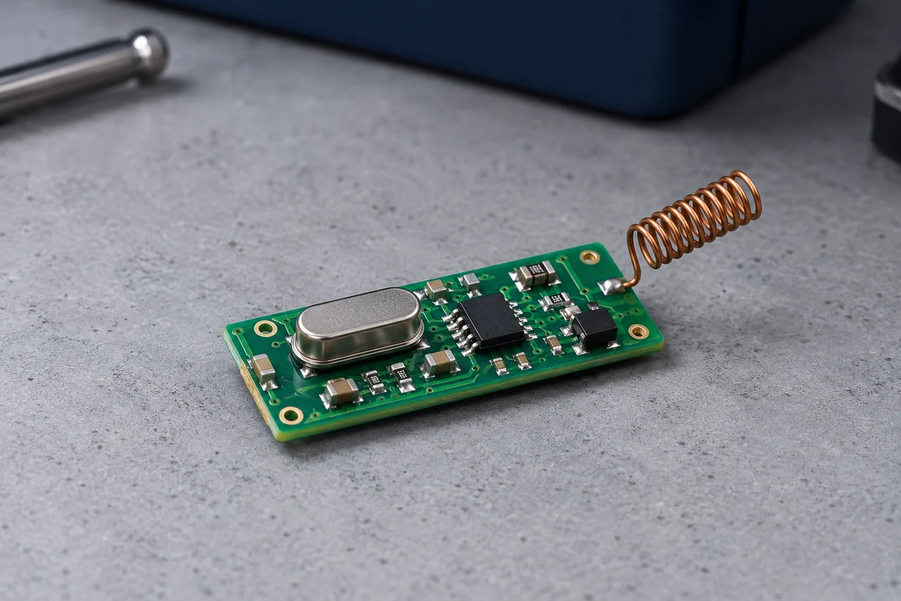
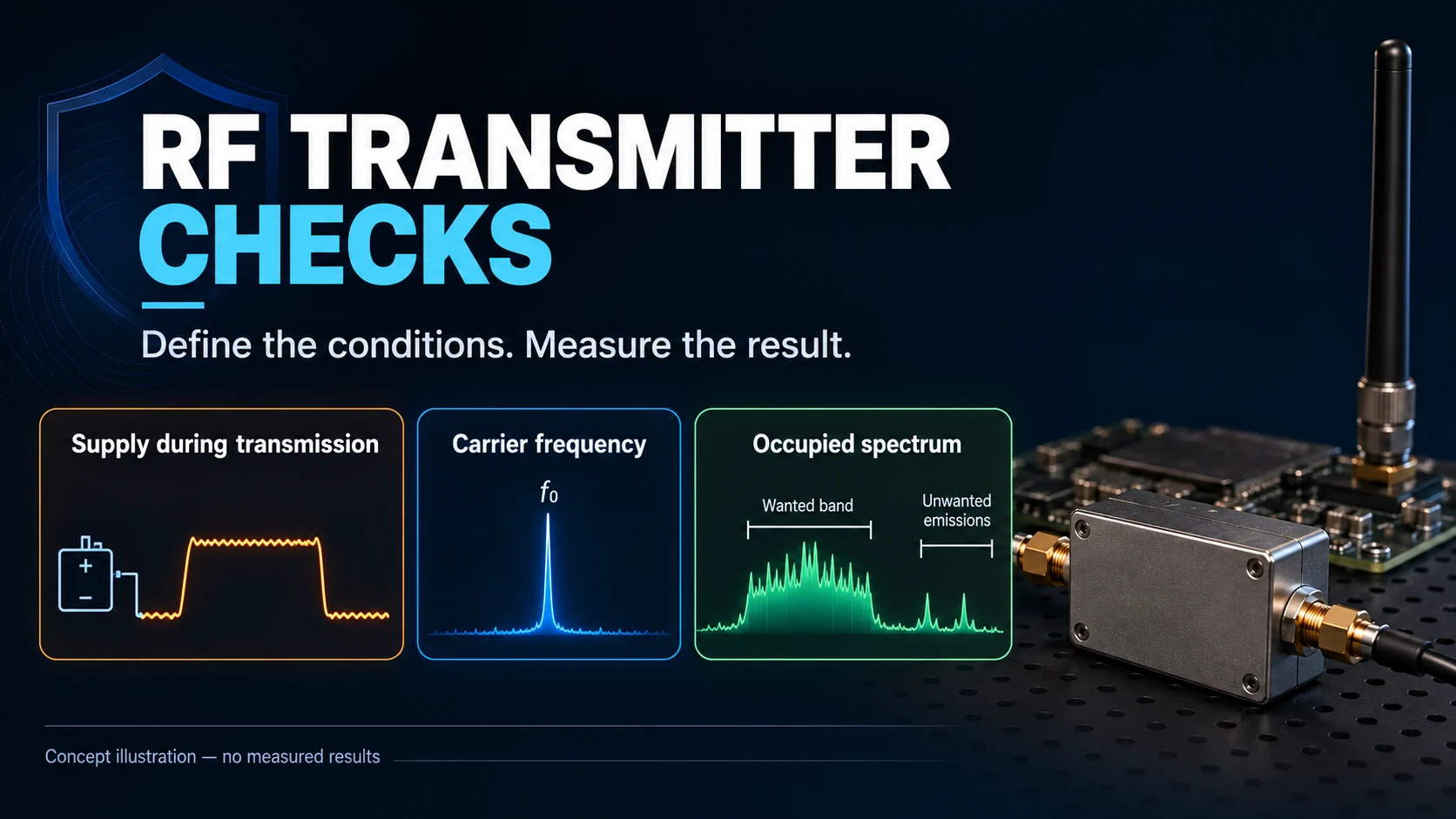
A transmitter sample can open a gate nearby and still fail the requirements of the finished product. That test confirms the receiver accepted the tested command; it does not establish frequency margin, emissions or production consistency.
The purchasing question is what happens when the battery, temperature, enclosure and component tolerances change.
Evaluate the transmitter with its intended receiver and antenna. Use bench measurements to isolate frequency and output problems, then use site tests to establish command performance.
The frequency reference, output network and antenna interact. A parts photograph shows their presence, but cannot establish their values, tolerances or performance.
- Does the carrier and modulation remain compatible with the receiver over the operating range?
- Does the assembled product meet its output and unwanted-emission requirements?
- Do multiple samples meet the same limits using a documented test method?
This guide connects those questions to the evidence a buyer can request: component requirements, RF measurements, sample variation and control of substitutions.
One successful sample is a functional check. Repeatability needs measurements from more than one sample.
Begin with a defined acceptance condition: receiver model, waveform, supply range, antenna, enclosure, operating environment and required command response.
Compare samples using the same receiver and test setup. Record hardware revisions, attempt counts and missed commands rather than treating similar housings or frequency labels as equivalent.
If a sample fails, keep the failing condition reproducible. The symptom “short range” can originate in output, carrier offset, antenna loss, power integrity or reception.
Assign separate limits to those measurements. A radio spectrum, an antenna impedance plot and a range result answer different questions.
Check the Frequency Reference
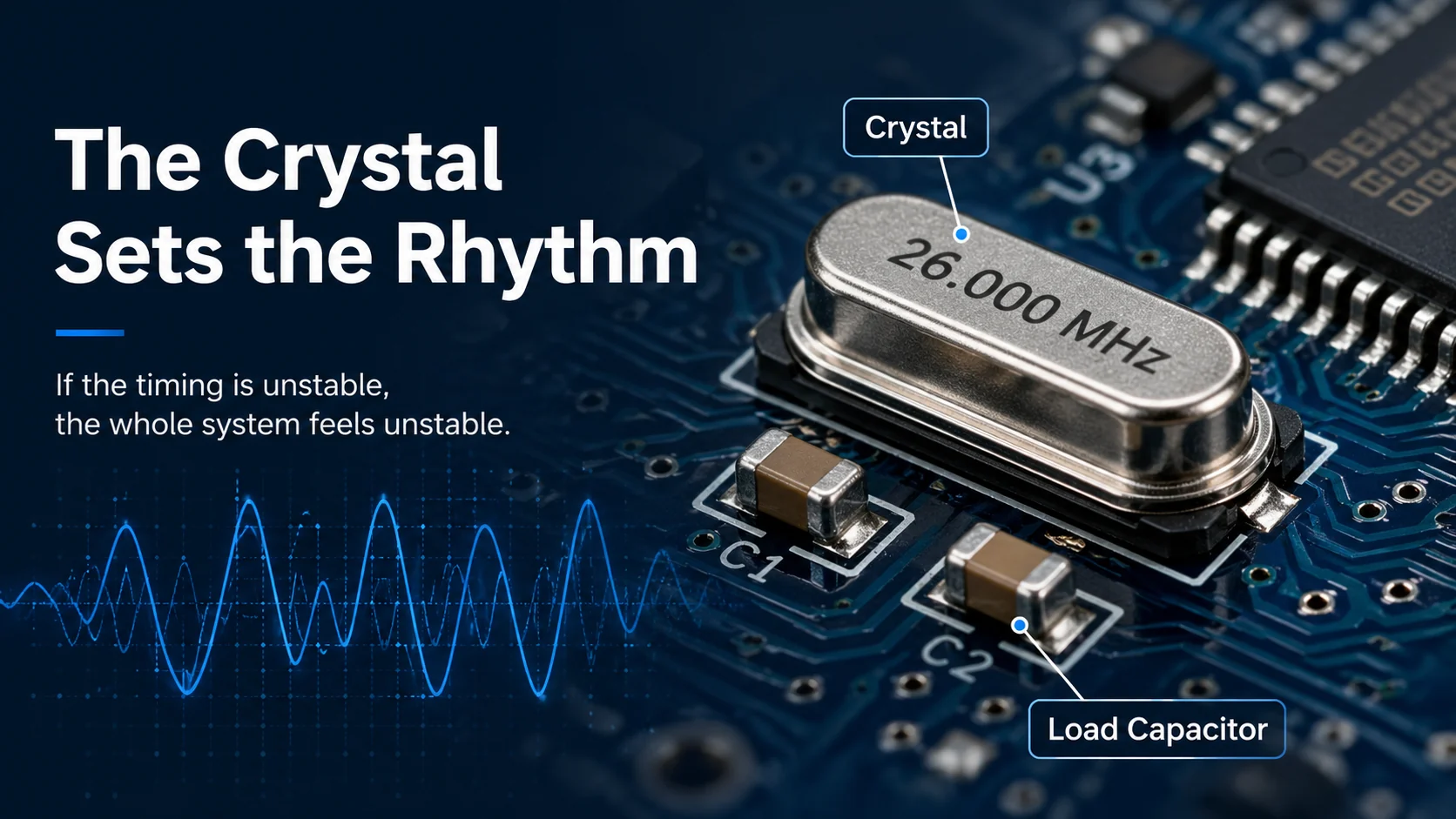
Identify how the transmitter generates its carrier: a crystal-referenced synthesizer, a SAW-based circuit or another architecture. A metal component package alone does not identify the function.
Some transmitter ICs use an internal calibrated reference. An external crystal is therefore not a universal requirement for a reliable remote.
In a crystal-referenced synthesizer, error in the reference shifts the RF carrier. The receiver’s own frequency error adds to the relative offset the link must tolerate.
Initial tolerance, capacitive loading, temperature and aging belong in that error budget. They cannot be replaced by the nominal frequency printed on the crystal.
TI’s frequency-offset note shows sensitivity degrading as transmitter and receiver frequencies separate. The tolerable offset depends on signal bandwidth and receive settings.
A close-range test can conceal offset because a strong received signal may still decode. Measure carrier offset directly and repeat the receive test at lower input levels.
Also distinguish carrier accuracy from data timing. Some products derive both from one reference; others use separate timing sources. The receiver must accept both.
For a crystal-based design, request the exact part specification and oscillator requirements from the radio IC datasheet.
- Nominal frequency: use the radio’s required reference frequency and operating mode.
- Total accuracy: budget initial tolerance, load error, temperature drift and aging at both ends.
- Load capacitance: check the crystal’s specified CL against the oscillator and board parasitics.
- Oscillator limits: confirm ESR, drive level and startup requirements for the selected IC.
- Verification: measure startup and carrier frequency across representative supply and temperature conditions.
For a simple two-capacitor oscillator, the effective load includes their series combination plus stray capacitance. CL is not normally the value to copy into each capacitor; use the IC’s design method.
Component substitution can change tolerance, ESR or load requirement while leaving the nominal marking unchanged. A substitute should be checked against the oscillator specification and measured on the product.
Separate Output Matching from Antenna Matching
A matching network transforms the impedance presented to the radio and antenna. It can also include a balun, filtering or DC blocking, depending on the output architecture.
Do not assume every chip output is a 50 Ω port. Follow the radio’s specified load and reference network before choosing the antenna-feed measurement point.
- Mismatch can reflect part of the incident power at an interface.
- Network components and feedlines can dissipate power.
- Antenna inefficiency can reduce radiated power even when the input match looks good.
Enclosure or hand proximity can change the antenna impedance and pattern. A change in range after assembly is a reason to measure those effects, not proof of one particular matching fault.

Ground return, component placement and RF trace geometry affect the network. Keep the reference layout’s critical geometry and use the actual PCB stackup when evaluating changes.
Copying the reference design is a useful starting point if the stated materials, dimensions and component packages are retained. It does not validate a different board or antenna automatically.
TI’s antenna matching guide recommends checking the final enclosure and in-hand condition for portable devices. Tuning an exposed board alone leaves the normal use condition unresolved.
- Conducted output into the specified load.
- Antenna impedance with the enclosure and relevant grip.
- Radiated performance and command success in intended orientations.
- Fundamental, harmonic and other unwanted emissions.
- Supply current and voltage during a complete command.
A low-reflection antenna is not necessarily efficient: a lossy network can also look well matched. Check radiation or a controlled link result as well as impedance.
Measure Unwanted Emissions
A transmitter must be evaluated beyond its carrier peak. Harmonics, modulation sidebands, oscillator leakage and switching transients can all matter to the applicable emission limits.
The intended modulated signal needs enough occupied bandwidth to carry its data. A filter should preserve that waveform while attenuating unwanted frequency components.
Harmonics occur at integer multiples of the carrier. Other peaks may be spurious signals, intermodulation or external interference; they should not all be labelled harmonics.
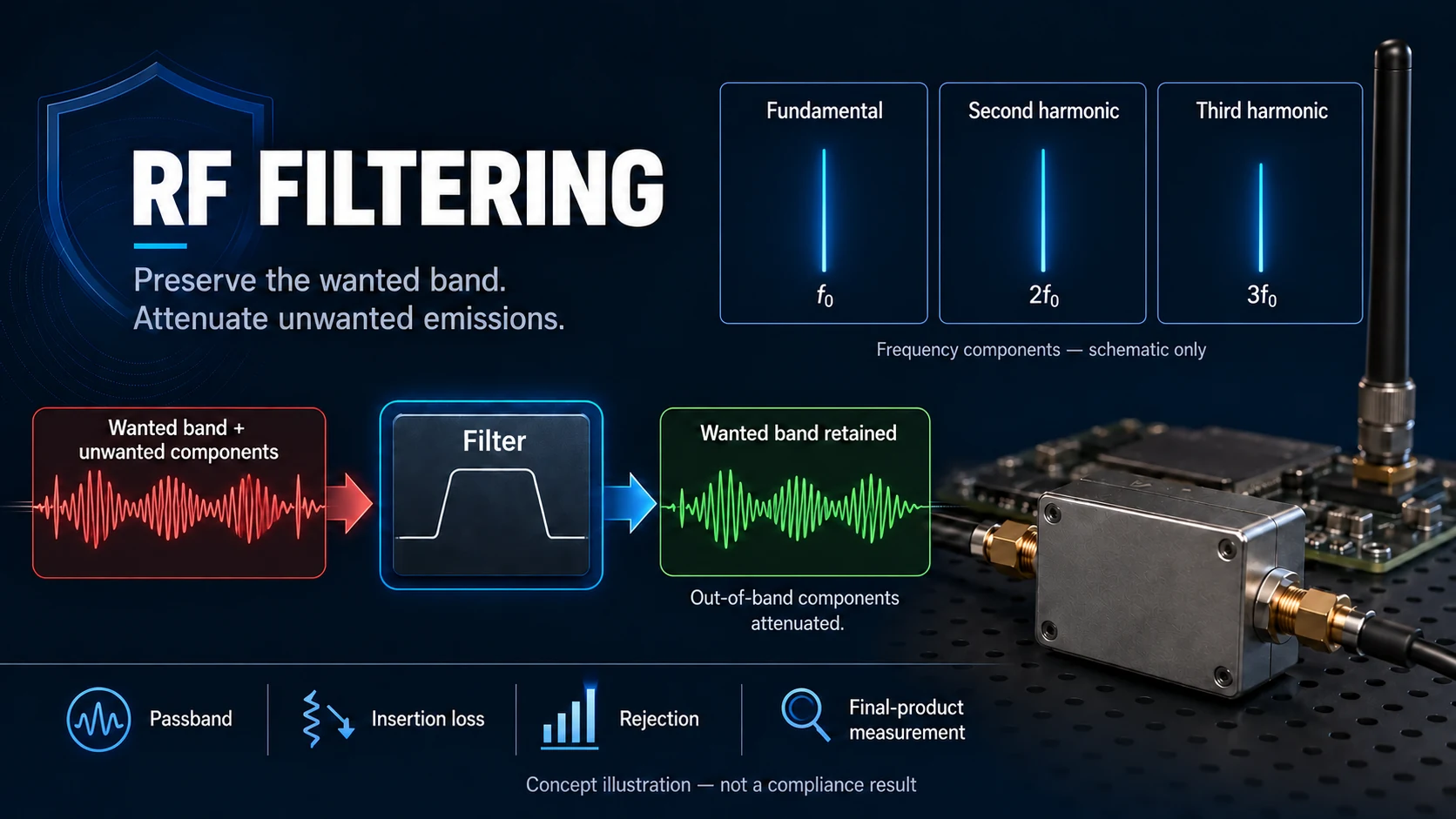
For a 433.92 MHz fundamental, the second and third harmonics are 867.84 MHz and 1301.76 MHz. Those are calculated frequencies, not measurements from the illustrations.
Applicable radio tests specify detector, bandwidth, distance or RF reference point and operating mode. A spectrum-analyzer screenshot without those settings is not evidence of compliance.
Check both conducted and radiated results where the requirements call for them. Output-network filtering cannot establish the emissions of the antenna, board and enclosure by itself.
A filter adds insertion loss and can affect waveform bandwidth. Choose it for the required passband and rejection, then measure fundamental output and unwanted emissions together.
The measured result should include the normal command and relevant repetition behavior. A continuous unmodulated carrier alone can miss switching or modulation effects.
Trace the Complete Signal Chain
If range changes after a board or enclosure revision, compare the changed hardware under the same test conditions before assigning the cause.
Several changes may act together: supply impedance shifts output; carrier offset changes receiver response; the enclosure changes antenna loading.
- Supply: maintains voltage through startup and transmission.
- Frequency reference: keeps the carrier within the receiver’s supported offset.
- Encoder/modulator: produces the correct framing and timing.
- Output network: presents the required load and filtering.
- Antenna: radiates with the intended efficiency and pattern.
- PCB: provides the specified geometry, stackup and return paths.
- Enclosure and installation: define the actual antenna environment.
Do not infer FR4 grade, component authenticity or solder quality from board color or a rendered photograph. Request the stackup, BOM requirements and relevant inspection or measurement records.
Test Function, Performance and Variation Separately
Functional testing establishes that the receiver accepts the command and produces the intended output.
Performance testing establishes margins under defined supply, temperature, orientation and interference conditions, with a stated response criterion.
Variation testing applies the same limits to multiple units and lots. Choose sample size and coverage based on the production risk rather than one attractive demonstration.
Use the same limits and fixtures when comparing production samples with the approved design.
Keep results identifiable by sample and hardware revision. Otherwise a good average can hide a failing unit, or a changed revision can be mistaken for normal variation.
Choose Conditions That Expose Weak Margin
Nominal room-temperature testing is a starting point. Extend it to the operating conditions the product is expected to meet.
At supply limits, measure RF output, frequency, command timing and reset behavior. Do not exceed the device’s recommended operating range to explore an unspecified claim.
At temperature limits, allow the sample to settle and use the intended battery or a documented battery model. A bench supply can hide coin-cell pulse problems.
For the final enclosure, compare representative grips and orientations. Mounting fixtures and test cables can themselves alter the antenna result.
Margin should be visible in the measurements at the required operating conditions.
Avoid a universal pass margin invented for every product. Establish limits from receiver compatibility, site requirements and the applicable radio rules.
Control Changes after Sample Approval
Record which crystal, RF passives, antenna geometry, stackup and firmware formed the approved sample. A nominally equivalent replacement may change oscillator or RF behavior.
When a supplier proposes a substitution, identify which measurements can be affected and repeat those checks on the assembled product.
This does not mean every component change needs every test. It means the verification should follow the physical role of the change and the existing authorization requirements.
- Frequency-reference change: check startup, drift and receiver offset tolerance.
- RF passive or package change: check matching, output and unwanted emissions.
- PCB stackup or layout change: recheck the RF network and antenna.
- Enclosure or antenna change: check installed impedance, radiation and command performance.
- Firmware timing change: check framing, repeats, latency, current and radio duty conditions.
Keep the Measurements Reviewable
For RF plots, keep the frequency span, detector, resolution bandwidth, calibration, supply and operating mode with the result. Identify the sample, not just the module family.
For range results, keep the receiver, antennas, enclosure, path and successful/attempted command counts. A photograph of an analyzer or open gate is not a test record.
For a claimed authorization or test report, confirm that the model, variant and antenna configuration correspond to the product being offered.
What to Resolve Before a Volume Order
Agree the hardware revision and acceptance conditions in writing. Define which sample represents the product and how a supplier will communicate material changes.
Resolve any sample failure with a repeatable before/after comparison. Record the actual correction rather than accepting a general statement that the RF was “optimized.”
Choose the production checks from the faults they can detect. A close-range button test may catch assembly failure while missing frequency drift or insufficient antenna performance.
If testing cannot resolve a requirement, identify the missing evidence. Do not turn an untested assumption into a promised range, battery interval or compliance claim.
This gives the buyer a concrete basis for comparing quotations: the specified design, measured margins, accepted variation and change process.
When sending a transmitter problem for review, include the receiver model, product revision, supply condition, enclosure, failure path and any measured frequency/output difference. Those facts narrow the next test.

About the Author
Eric Huang
RF Remote Controls & Controllers Specialist
I work with trade buyers on custom RF remote and controller projects, automotive remote requests and aftermarket gate and garage remote sourcing. These guides help you define product requirements and plan sample checks before ordering.
Share your application or original system, target market and question to discuss the next steps.
Keep reading
Related articles
RF Remote Collisions: Check the Hardware and Protocol
Separate one-way repetition from receive-capable channel sensing and two-way acknowledgments, then test command overlap and duplicate handling.
Read next OEM/ODMOEM or ODM for RF Remotes: Define the Scope
Compare who designs, who owns the results, how changes are approved and what evidence is delivered before choosing an OEM or ODM arrangement.
Read next RF EngineeringOne Remote, Many Doors: How Shared RF Control Works
Understand how receivers recognize enrolled remotes, map buttons to groups, and manage shared access without confusing capacity with radio reliability.
Read nextDiscuss Your Project or Replacement
Share your application or original system and your question to discuss the next step.
RF questions by email
Ask Eric About Your Remote or Receiver
Describe your remote or receiver, the issue and what you have already tried. Add model details and your country if available.
Opens a draft in your email app. Review it, attach any photos and send your message.