
Separate receiver sensitivity from production screening, verify every defined control function, and set clear powered-test and retest conditions before release.
Reading mapArticle sections6 sections
An assembled wireless receiver controller powers up. Its indicator lights, and a paired remote makes a relay operate. That is a useful first check, but it is only one operating point.
Before shipment, the questions become more specific: does reception meet the model's requirement, does every defined control function work, and does operation remain stable during the specified powered test? A missed command, an incorrect mode or an intermittent reset needs a different investigation.
The practical approach is to separate reception, control functions and extended operation, then keep the evidence from each stage. A unit should reach packaging because it passed the agreed release criteria.
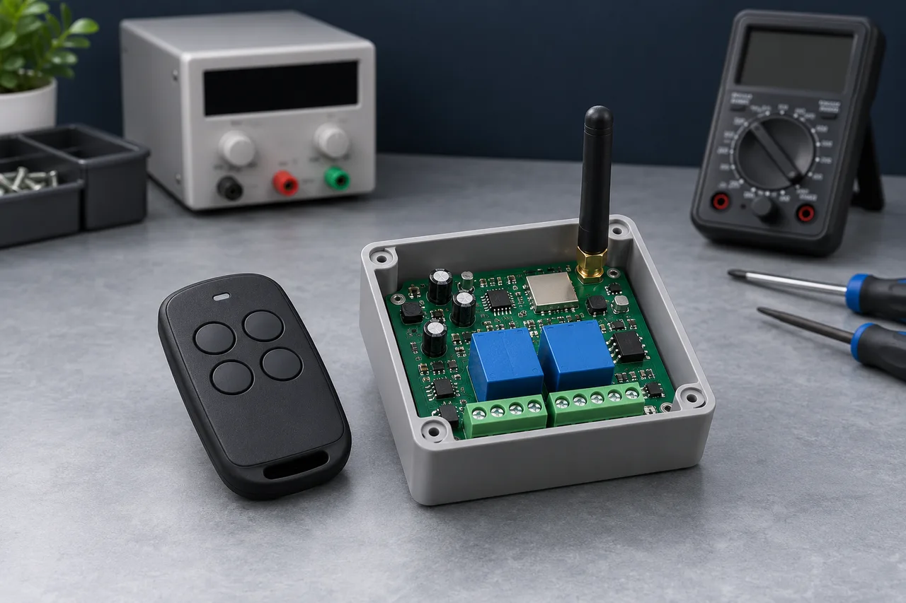
Define the Conditions Before Calling a Test Passed
A useful workflow is assembly and basic power checks, reception checks, functional checks, a specified powered soak or burn-in, review and retest of exceptions, then release for packaging. The station order can vary; the required checks and release gates must remain clear.
Start with the model, hardware revision, firmware and order specification. Define supply conditions, radio settings, antenna or enclosure configuration, output load where applicable, test duration or repetitions, and the result that counts as a pass. State which checks cover every unit and which are performed on samples.
Do not choose an acceptance limit after seeing the result. A borderline unit needs the prescribed disposition, and a doubtful fixture needs investigation before either a pass or a failure is assigned.
Separate Reception Screening from Sensitivity Measurement
Use a compatible transmitter or test waveform for the model's frequency, modulation and coding. A signal at the correct frequency is not enough if the receiver cannot decode its format. Control the transmit sequence and count successful receptions over a defined number of attempts.
Receiver sensitivity is the minimum input level that meets a specified error or reception criterion under specified conditions. The waveform, data rate, receiver bandwidth, packet or command format, supply and measurement reference matter. A single successful command at a weak signal level does not establish that threshold.
TI's CC1101 datasheet illustrates this dependence by specifying sensitivity together with radio settings and a packet-error criterion. Its chip figures are not automatically the sensitivity of an assembled controller.
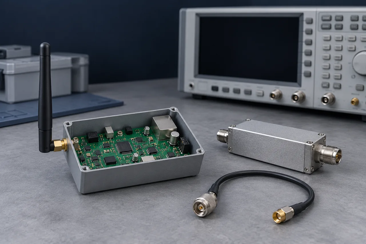
For a conducted measurement, define the RF input reference plane and account for cable and attenuator loss. A calibrated radiated setup can assess the complete antenna and enclosure path, but it uses a different measurement reference. Keep those results distinct when reporting performance.
A fixed-distance transmitter or a fixed attenuation fixture can be useful for production screening. Unless the applied signal and threshold method are characterized, describe the result as reception performance or consistency screening rather than a measured sensitivity value in dBm.
Keep transmitter output, battery or supply condition, antenna orientation, spacing and fixture arrangement stable. Nearby interference, enclosure changes and worn connections can shift the result. Reference units and fixture checks help detect a changed test setup; a reference unit alone does not calibrate an absolute RF level.
Keysight's receiver test guidance connects input level with a defined BER or PER limit. For the difference between a component specification and an installed link, see our receiver sensitivity guide.
Check Every Defined Function and the Actual Output
Once a valid command can be received, follow it through the controller. Verify the intended channel, its timing and its final state. An indicator or a relay click alone does not establish that the output contacts switched correctly.
Build the checklist from the model's actual features. Depending on the specification, this may include remote enrollment and deletion, momentary operation, latching, interlocking, delays, external inputs and custom logic. Do not assume every controller supports all of these.
- Exercise every defined channel and verify the actual output, not only the status indication.
- Check entry into each supported mode and the resulting behavior on subsequent commands.
- Verify enrollment, deletion and rejection of unauthorized or deleted credentials where specified.
- Check repeat commands and transitions between outputs, including the specified interlock behavior.
- Confirm power-up state, stored settings and recovery after a planned power cycle against the specification.
Use the specified load and an appropriate output measurement. Resistive, inductive and small-signal loads can place different demands on relay contacts. Testing without a load answers a different question from switching the intended load.
OMRON's relay guidance explains that reliability depends on the switching conditions and load. Choose test cycles and loads within the component and product requirements; do not turn a release check into an uncontrolled endurance test.
Define What Extended Powered Operation Is Meant to Find
Some faults appear immediately; others emerge after sustained operation or repeated commands. Unstable connections, abnormal supply behavior and intermittent control faults may become visible during an extended test. A symptom alone does not identify the failed component.
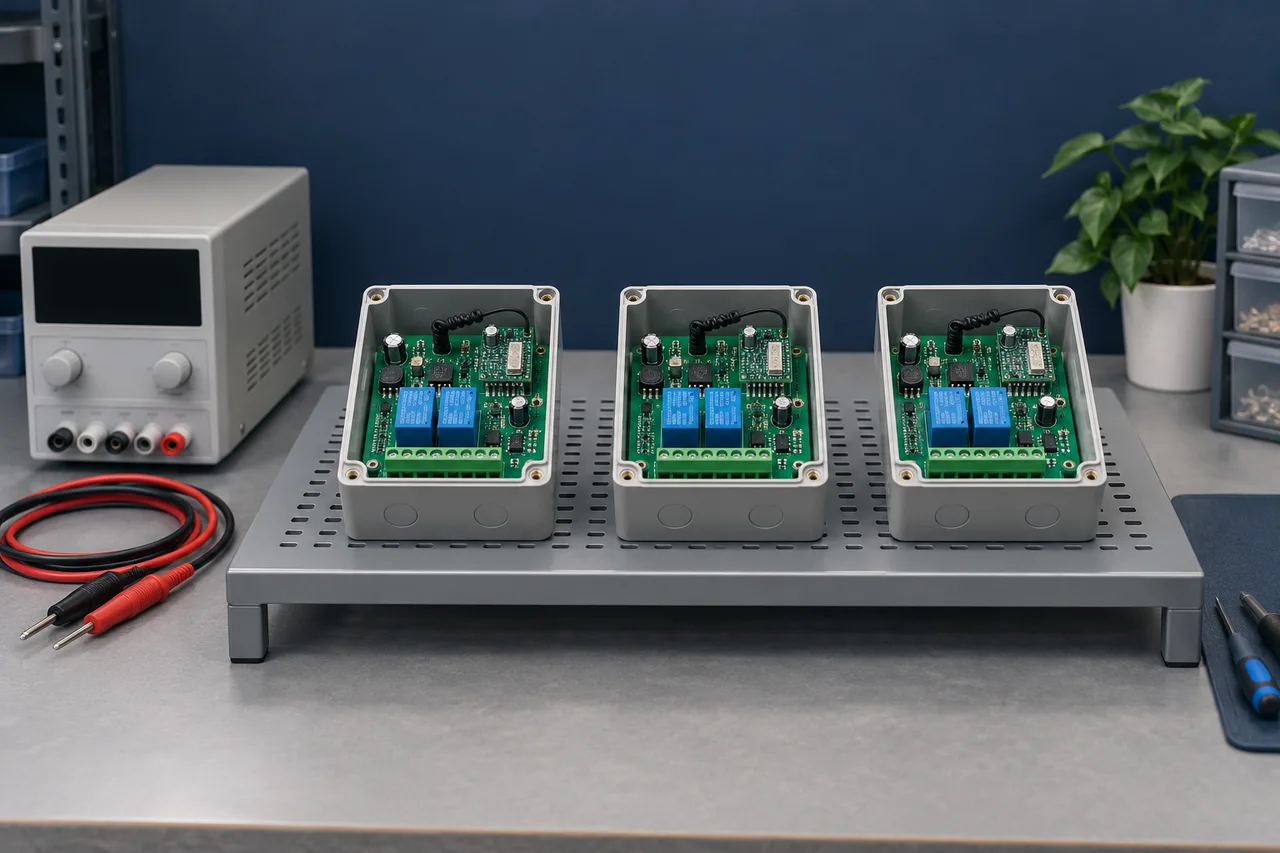
Set the duration, supply, ambient conditions, enclosure state, load and action cycle in the model's inspection plan. A powered soak at ordinary conditions and a deliberately stressed burn-in are different procedures. The test name should describe what was actually performed.
Record resets, missed commands, unintended output changes and interruptions throughout the test, using suitable monitoring for the fault of interest. A lamp that remains on, or a successful command only at the end, can miss a brief fault in the middle.
Specify whether repeated output switching is needed and how much is permitted. More hours or more relay cycles are not automatically better: inappropriate stress can consume contact life or create damage that the normal application would not cause.
Passing a finite soak screens for problems detectable under those conditions. It does not prove service life, field interference tolerance or long-term reliability. Those questions require the appropriate design validation and qualification evidence.
Keep Exceptions on Hold Until Their Disposition Is Complete
Separate a failed unit from released stock and record the symptom, unit or lot identity, firmware, fixture and test conditions. Check the setup as well as the product: a faulty transmitter, connector or supply can make several good units appear defective.
After repair, repeat the failed test under the relevant conditions and cover other checks that the repair could affect. Work on the supply or firmware can affect reception, timing and stored settings, so repeating only one button press may be insufficient.
For an intermittent fault, use the defined reproduction and observation procedure. If the cause remains unresolved, keep the unit on hold under the inspection plan. Repeating a test until one pass appears is not evidence that the original fault has been removed.
If similar failures recur across a lot, investigate the shared cause and assess other potentially affected units. Correcting one board does not close a batch-level issue. Release requires the applicable retests and a recorded disposition.
Make Batch Consistency Reviewable
A good sample establishes a starting point. A shipment needs evidence that the agreed production checks were applied consistently. Comparable results need comparable fixtures, conditions, limits and revision control.
- Identify the model, hardware and firmware revisions, lot or unit, and test-plan version.
- Record reception conditions and results without presenting a screening result as an absolute sensitivity measurement.
- Record channel and mode coverage, output load, powered-test duration and monitored exceptions.
- Keep repair history, retest outcomes and release status linked to the affected units.
- Agree the test coverage and any customer-specific conditions before production.
At Dongguan Fengxian Electronics Technology Co., Ltd., this is the basis for discussing receiver-controller inspection requirements: what needs to be verified, under which conditions, and what evidence supports release. The exact method, duration and coverage should be confirmed for the selected model and order.
The buyer's benefit is practical: fewer unexplained differences between units and clearer information when installation issues arise. Reception, functions and extended operation each contribute evidence; none substitutes for the other two.
A controller is ready for shipment when its defined release checks are complete and exceptions are resolved with evidence.

About the Author
Eric Huang
RF Remote Controls & Controllers Specialist
I work with trade buyers on custom RF remote and controller projects, automotive remote requests and aftermarket gate and garage remote sourcing. These guides help you define product requirements and plan sample checks before ordering.
Share your application or original system, target market and question to discuss the next steps.
Keep reading
Related articles
Receiver Sensitivity: Compare the Test Conditions
Read a sensitivity figure with its waveform, bandwidth and error target, then test whether receiver performance is limiting the installed link.
Read next OEM/ODMComparing Gate Remotes with the Same Housing
Compare board materials, button assemblies, RF performance and production checks when similar-looking gate remotes carry different quotes.
Read next RF EngineeringDifferent Codes, Same Channel: Why RF Remotes Can Collide
Separate remote identity from radio access, then check how overlapping frames, airtime, repeat timing and two-way protocols affect command delivery.
Read nextDiscuss Your Project or Replacement
Share your application or original system and your question to discuss the next step.
RF questions by email
Ask Eric About Your Remote or Receiver
Describe your remote or receiver, the issue and what you have already tried. Add model details and your country if available.
Opens a draft in your email app. Review it, attach any photos and send your message.