
Choose a matched transmitter and decoded receiver, check the control interface, and test one low-voltage load before adding more functions.
Reading mapArticle sections9 sections
If an RF receiver detects a signal but the relay does not behave as expected, check what the receiver output actually represents. A raw data output and a decoded control output serve different purposes.
For a first build, use a documented handheld transmitter and a matched receiver with decoded control outputs. This avoids having to design the radio, packet format and decoder at the same time.
The goal here is one button controlling a small low-voltage lamp or buzzer. There is no universal wiring diagram: supply voltage, output levels and relay trigger behavior must come from the selected boards.
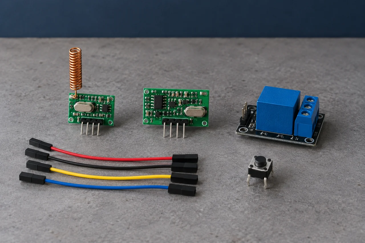
RF and Infrared Take Different Paths
An infrared remote sends modulated light to a light-sensitive receiver. It generally needs a usable optical path, although reflections can sometimes carry the signal around a room.
Walls and opaque objects can interrupt that path. This is why an infrared remote may work when aimed at a wall yet fail from another room.
RF uses radio waves. A path through a non-metal partition may be usable, but metal, reinforced concrete and antenna placement can still reduce received power enough to prevent decoding.
Frequency choice depends on the country and application. The EU SRD decision includes conditional 433 MHz entries; US control transmitters can operate under rules such as 47 CFR §15.231. Neither 315 MHz nor 433 MHz is a worldwide permission to transmit at any power.
The Radio Link Needs a Decoder
Separate three jobs: transmit a coded command, receive and validate it, then switch the load. Some boards combine several jobs; a bare radio receiver usually does not.
- Transmitter: a finished remote with a documented code format, or a radio driven by an encoder or microcontroller.
- Receiver and decoder: a matched board that identifies the command and produces a defined output. A raw DATA output carries received bit timing, not a ready-to-use switch signal.
- Load interface: a relay module or electronic switch whose input is compatible with the decoded output. It needs its own correctly rated supply.
The intended chain is button → encoded RF command → receiver → valid decoded command → load driver. Matching only the printed frequency leaves the decoding step unresolved.
Choose the Parts as a Set
Buy the radio pair with its pinout and operating instructions. Confirm whether the receiver already includes a decoder and relay before ordering another board.
- A handheld transmitter and receiver documented to use the same frequency, modulation and code format.
- A decoded receiver output, or the correct decoder/microcontroller if the receiver supplies raw data.
- A relay module with an onboard driver, if the receiver does not already include the load switch.
- Receiver and relay supplies at their specified voltages, with enough current for the relay coil.
- The transmitter battery type specified by its manufacturer.
- A small low-voltage lamp or buzzer and suitably rated wiring.
- A nonconductive enclosure with room for the prescribed antenna.
- A multimeter and the board documentation; an oscilloscope helps if a pulse output is too brief to measure.
Two 433.92 MHz boards can still be incompatible. They may use different modulation, pulse timing, addresses or rolling-code formats. A transmitter and receiver sold as a documented pair reduce this uncertainty.
Check the Transmitter Interface
A finished handheld remote already contains the button, coding circuit and radio. Check its battery polarity and pairing procedure. A bare transmitter with VCC, GND and DATA needs an external source of correctly timed data.
Use the module’s recommended supply range, not its absolute maximum rating. Check DATA-pin voltage limits as well: a board powered at 3.3 V may not accept a 5 V control signal.
Holding a bare transmitter DATA pin high may produce a carrier, but it does not create an addressed button command. Follow the encoder or microcontroller design for that particular receiver.
Connect the Decoded Output to the Load Driver
Find the receiver’s decoded channel output and its active level. Check output voltage, source/sink current and the relay module’s input requirements before connecting them. Do not connect raw RF DATA to relay IN.
A relay coil must use a suitable driver and inductive suppression; a receiver GPIO should not power it directly. If the relay board has a driver, follow its supply and ground instructions. Some isolated boards have separate coil and logic supplies.
For a normally off DC lamp, the contact circuit can be load-supply positive → COM → NO → lamp → load-supply negative. Confirm the lamp voltage and relay’s DC contact rating. The radio’s logic supply need not be the lamp supply.
Keep this circuit at low voltage. Relay contact markings alone do not establish that a board, enclosure or wiring arrangement is suitable for mains. Turn power off before changing connections.
Test One Stage at a Time
Check the decoded output before connecting the load. Then verify the relay input, contact closure and lamp separately. A relay click confirms coil motion; it does not prove the load has power.
- Compatibility: use the documented radio pair and complete its pairing procedure.
- Supply: measure voltage at the receiver and relay pins, including when the coil energizes.
- Output: confirm momentary, toggle or latch behavior. These are different functions even when boards look identical.
- Control interface: verify the active level and current rating; add the prescribed driver or level interface if required.
- Contacts: check COM/NO continuity with power removed from the load circuit.
- Antenna: install the specified antenna outside metal shielding and test with the final enclosure.
At 433.92 MHz, c/(4f) is about 17.3 cm. This is the free-space starting length for a quarter-wave wire monopole, not a rule for every antenna. Ground size, enclosure and matching matter; do not straighten a deliberately designed helical antenna.
Add Functions After the Basic Link Works
Multi-channel control needs separate decoded channels and a receiver mode suited to each load. Decide whether each button should hold, toggle or select an output before choosing the board.
A microcontroller can add a timeout, reject repeated commands or report status. Its inputs must still tolerate the receiver output voltage, and reset should leave the load in the intended state.
Simple fixed-code demonstration modules are not a basis for secure access control. A stored code can be replayed if the receiver accepts the same command again.
For a door or lock, use a complete, documented access-control system with appropriate authentication and safety functions. A rolling-code encoder name alone does not establish that the receiver, key provisioning or actuator is secure.
Checks Before Enclosing the Project
- Use equipment permitted for the intended country and application.
- Stay within the recommended supply, pin and contact ratings.
- Keep the first load low voltage and disconnect power before rewiring.
- Check output behavior after receiver power-up, loss of signal and a long button press.
- Follow the antenna instructions and repeat the test after closing the enclosure.
- Keep the demonstration separate from locks, gate operators and other safety-critical loads.
Record What You Built
Write down the exact board models, pin connections, supply voltages and receiver mode. This makes a later fault traceable instead of relying on the appearance of the modules.
For each button press, observe the decoded output, relay contact and load response. If one stage fails, investigate that stage before changing the radio.
A successful bench test establishes the basic control chain. Range and reliability still need testing at the intended locations with the final antenna, enclosure and power supply.
A usable RF command needs both a compatible decoder and a correctly rated load interface.

About the Author
Eric Huang
RF Remote Controls & Controllers Specialist
I work with trade buyers on custom RF remote and controller projects, automotive remote requests and aftermarket gate and garage remote sourcing. These guides help you define product requirements and plan sample checks before ordering.
Share your application or original system, target market and question to discuss the next steps.
Keep reading
Related articles
How to Test RF Remote Range with Your Receiver
Define the required operating locations, count missed commands, and separate antenna, supply and interference problems before comparing range claims.
Read next TroubleshootingDiagnose Short Range on a 433 MHz Remote
Use controlled substitutions and supply, antenna and decoding checks to find why a remote works at one installation but fails at another.
Read next Rolling CodeGarage Remote Security: Replay and Lost Remotes
Check what fixed and rolling code protect, why chip markings are incomplete evidence, and how the installed receiver handles a lost remote.
Read nextDiscuss Your Project or Replacement
Share your application or original system and your question to discuss the next step.
RF questions by email
Ask Eric About Your Remote or Receiver
Describe your remote or receiver, the issue and what you have already tried. Add model details and your country if available.
Opens a draft in your email app. Review it, attach any photos and send your message.