A transmitter module is not reliable just because it can send a signal. Real quality depends on stability, clean output, tuning margin, and repeatable mass production.
Reading mapArticle sections9 sections

Many problems with transmitter modules are not because they cannot work.
The problem is that they only work when everything is "just right".
A sample can transmit a signal, but that does not mean mass production will be stable. A spectrum analyzer can show a signal, but that does not mean the signal is clean. A customer can open the gate at close range, but that does not mean the product is truly reliable.
Crystal oscillators, matching circuits, and filters may look like small details on the circuit board. But in the end, they become the real user experience in the customer's hand.
- Can the remote control work from a long distance?
- Is the response stable?
- Will the quality stay consistent in mass production?
This article is not meant to explain RF circuits like a textbook. I want to talk about something more practical: why a good transmitter module is not just about whether it can transmit a signal, but whether it has the confidence to stay stable for a long time.
Customers will not discuss crystal accuracy, impedance matching, or harmonic suppression with you. They will only say: "This remote control does not have a good range."
Once, I tested a transmitter module and felt something was wrong. It was not broken. When I pressed the button, there was a signal. The receiver responded. The spectrum analyzer also showed a waveform.
But with the same battery, the same case, and the same 433 MHz frequency, another remote control could work from dozens of meters away, while this one could only work from around ten meters.
That simple customer complaint turns all the complicated reasons into one very direct judgment: your product is not reliable enough.
So the real difficulty of a transmitter module is never just "can it transmit?" The real questions are whether it can transmit stably, transmit cleanly, and keep the same performance in different environments, different batches, and different customers' hands.
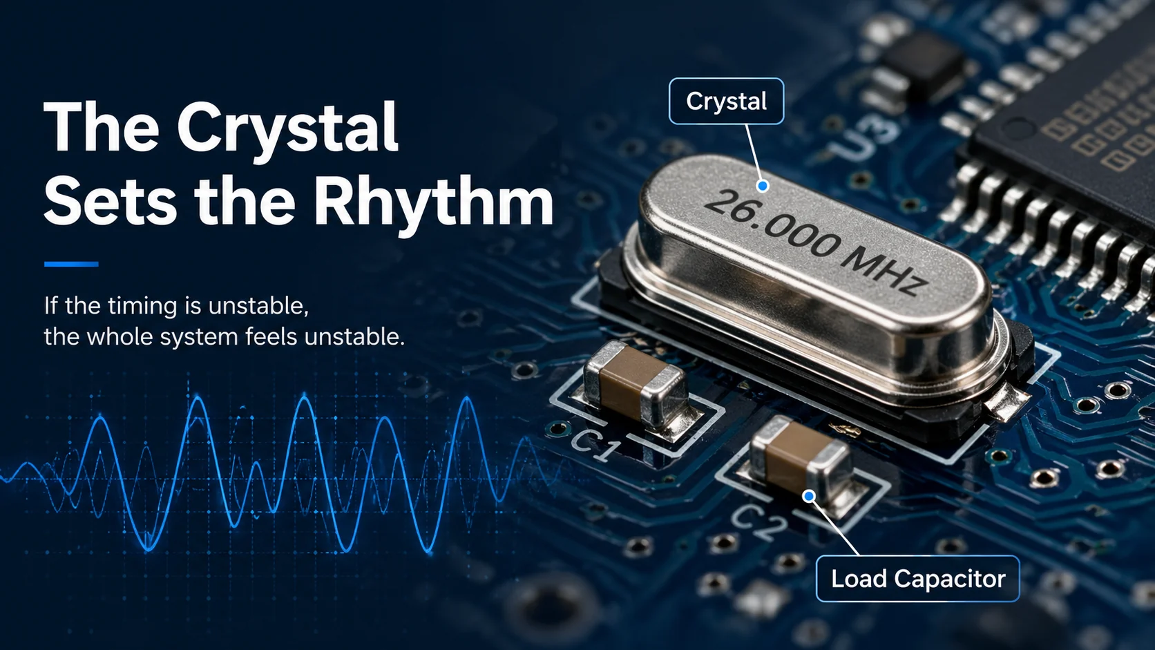
The Crystal Is Not a Small Part. It Is the Rhythm of the Whole System
Many people easily ignore the crystal oscillator when they first look at a transmitter module. It is just a small metal part with two pins, usually with two small capacitors beside it. On the schematic, it only takes a small space.
So it is easy to think: "Almost the same should be fine, right?"
But the crystal is the rhythm of the whole system. If the rhythm is not stable, everything after it will also become unstable.
You can imagine a transmitter as a band. The chip is the singer. The matching network is the sound mixer. The antenna is the speaker. The filter is the post-processing. Then the crystal is the beat.
That is why some modules can work, but still feel unreliable. At close range, they work fine. At a longer distance, they start to become unstable. In an open area, they work fine. When there is more interference, they start to fail.
This kind of instability is often not because one part is completely broken. It is because the basic reference of the whole system is not stable enough.
Customers will not say: "Maybe your crystal load capacitance is not matched." They will only say: "Sometimes this remote works, sometimes it does not."
So how should we choose a crystal? For beginners, I think there are a few practical points to remember.
- First, read the chip datasheet. Do not guess. Use the frequency required by the chip and follow the recommended load capacitance range.
- Second, look at the accuracy. Numbers like +/-10 ppm, +/-20 ppm, and +/-30 ppm are not decorations.
- Third, look at the load capacitance. The CL value marked on the crystal, such as 12 pF or 16 pF, is not just extra information.
- Fourth, look at batch consistency. One board working normally in the lab does not mean the whole batch will work normally.
Many people think that if a crystal is marked 26 MHz, then it must be exactly 26 MHz. That is not true. It is close to the marked frequency only under specific load conditions.
A good sample but failed mass production is one of the scariest things in product development. The crystal is a small part that looks unimportant, but once it causes problems, it is very hard to explain.
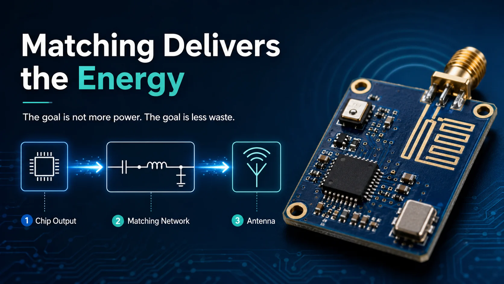
The Matching Circuit Solves One Real Problem: Is the Energy Being Wasted?
Impedance matching sounds very technical. But in simple words, it means: has the energy you send out really reached the antenna?
Many people think that if the transmitting distance is not enough, the power must be too low. Not always. Sometimes the energy is there, but it is wasted on the way.
- It is reflected back.
- It is lost.
- It does not enter the antenna smoothly.
Then what do you see in the final product? The board gets a little warm. The range becomes shorter. The performance drops after putting it into the case. The result changes when your hand gets close to the antenna.
RF circuits care about layout. They care about grounding. They care about trace length. They can even feel your finger getting close. This is not being too sensitive. This is simply the reality of RF circuits.
Some people say: "Just copy the reference design for the matching circuit." This sentence is not completely wrong, but it is only half true.
A reference design works under a specific PCB, a specific antenna, a specific case, and specific test conditions. If your board size changes, the antenna position changes, the case material changes, or the ground plane size changes, the matching may also change.
- Output power.
- Antenna matching.
- Harmonics.
- Real distance.
- Performance after putting the board into the case.
There is a very real distance between "it can transmit on paper" and "it works well as a product". Many low-cost modules do not fail because of the chip. They fail because of the matching.
Filtering Is Actually About Boundaries
In the past, I understood filtering in a very simple way. I thought it was just to make the signal cleaner. Later, I realized there is a deeper meaning behind it: it is about boundaries.
A transmitter cannot only care about "what I want to send". It must also care about "what I should not send".
The main frequency is the message you really want to send. Harmonics, spurious signals, and noise are the things you accidentally send out.
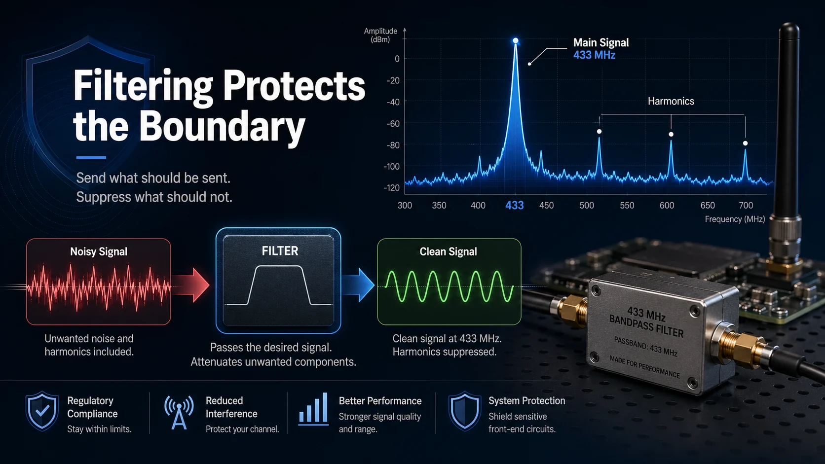
You want to transmit at 433 MHz, but the second and third harmonics may also come out. The remote control may still open the gate. But from the view of the whole wireless environment, the signal is already not clean.
That is why certification tests check these things. Wireless space is a public resource. You cannot send out unwanted signals just because your own device can work.
Filtering helps the circuit keep this boundary: send out what should be sent, and suppress what should not be sent. This is not decoration. This is discipline.
But stronger filtering is not always better. If the filtering is too heavy, the main frequency power may also be reduced. A proper filter makes the signal clean. Too much filtering may damage the signal.
RF circuit design is not about memorizing answers. It is more like tuning a musical instrument. You cannot only look at the parameters and assume the sound must be good.
The Real Beginner Mistake Is Looking at One Component, Not the Whole Chain
A transmitter module can easily mislead people. It makes people think the problem must come from one single point. If the range is not good, blame the antenna. If the frequency is unstable, blame the crystal. If the signal is not clean, blame the filter.
But many times, the problem is not one single point. It is the whole chain affecting each other.
- The crystal provides the reference.
- The chip handles modulation and output.
- The matching circuit decides whether energy can be sent out.
- The filter decides whether the signal is clean.
- The antenna decides whether energy can become useful radiation.
- The PCB layout decides whether these parts interfere with each other.
- The case and installation environment can change the result again.
That is why some boards perform well in the lab, but become worse after being put into the case. That is why samples can be good, but mass production becomes unstable.
From "Usable" to "Good" to "Repeatable" Are Three Different Levels
The first level is usable. You press the button, there is a signal, the receiver responds, and the distance is acceptable.
The second level is good. The range is stable. The response is quick. The performance does not drop too much after putting it into the case. The customer does not need too much explanation after receiving it.
The third level is repeatable. One board works like this today, and one batch works the same tomorrow. When another group of workers assembles it, the result does not change too much.
A real commercial product does not depend on one good sample. It depends on repeatability.
Repeatability is product capability. Repeatability is factory capability. Repeatability is the reason customers dare to place another order.
Truly Advanced Design Leaves Margin for Imperfection
The hardest part of engineering is not chasing perfect conditions. It is admitting that the real world is not perfect.
Many beginners design circuits as if everything is ideal: the battery voltage is stable, the component values are perfect, the antenna environment is ideal, the case has no effect, and every batch is exactly the same.
But in the real world, batteries run low. Soldering can vary. Cases can absorb signals. Customers may install devices in strange places. Supplier batches can change.
So the quality of a design is not only about whether it can run under ideal conditions. It is about how much margin is left when conditions are not ideal.
There is no margin when a product only works under perfect conditions. It is only barely standing. It is not standing firmly.
A truly good low-cost design does not remove the key things. It keeps the bottom line within limited cost.
So Now, When I Look at a Transmitter Module, I Look for Long-Term Thinking
Long-term thinking is not a slogan. It means when you choose a crystal, you do not only care about saving a few cents. It means when you design the PCB, you do not route the RF trace casually.
It means when you design the matching circuit, you know you need to leave space for tuning. It means when you could remove a small component to save cost, you still understand that the risk may be passed to the customer.
Low-cost products can also be made seriously. Low cost does not mean rough. Cheap does not mean careless. Good value does not mean passing risk to the customer.
- The crystal should be stable.
- The matching should be smooth.
- The filtering should be clean.
- The structure should not damage the antenna.
- Mass production should not go out of control.
In the End, Circuits Are Not About Being Smart. They Are About Being Honest
A transmitter module is not something you can explain with empty words. If you say the range is long, testing will show it. If you say the frequency is accurate, the spectrum analyzer will show it. If you say the signal is clean, certification testing will show it.
Circuits will not act for you. They are cold, but they are fair. Where you are lazy, they will make you embarrassed sooner or later. Where you are serious, they will reward you in some small detail one day.
When a customer says "This remote control is quite stable", "The range is better than the previous one", or "This batch is almost the same as the last batch", those words are the best praise for a product.
A Good Transmitter Module Is Reliability Compressed Into a Circuit
Now when I look at a transmitter module, I am not only looking at the crystal, inductor, capacitor, and antenna. I am also looking at the working attitude behind it.
Which parts cannot be saved? Where should margin be left? Where should we not cut corners just because the customer cannot see it?
People outside the industry may not notice these things at first glance. But the product will speak for you. When it is stable, it speaks for you. When it passes certification, it speaks for you. When the whole batch stays consistent, it also speaks for you.
The user presses the button. The gate opens. The signal arrives. The device responds. The user does not need to know how the crystal is selected, how the matching is tuned, or how the harmonics are suppressed. But the user can feel one thing: this product is reliable.
Behind the word "reliable", there is design, testing, discipline, margin, and no laziness. It is also the simplest and most valuable dignity of a product.
During product export, remote control sourcing, or transmitter module mass production, what is the most difficult unstable problem you have ever met? Was the sample good but the mass production bad? Was the range unstable? Did the performance drop after changing the case? Or was the customer's installation environment too complicated?
About the Author
Eric Huang
RF Remote Controls & Controllers Specialist
Hi, I'm Eric Huang, with 10+ years of experience in RF remote controls and controllers. I combine technical expertise with international trade knowledge to provide businesses with reliable, high-quality solutions. My goal is to ensure every client finds a trustworthy product.
Feel free to share your thoughts or ask questions. Let's connect!
Keep reading
Related articles
RF Remote Concurrency and Collision Avoidance: From the Physical Layer to the Protocol Layer
When many RF remotes share the same channel, reliability depends on how the system handles shared spectrum, interference, timing, hidden terminals, acknowledgments, and recovery.
Read next OEM/ODMOEM or ODM? You Think You're Choosing a Production Method, But You're Actually Choosing Your Future
For hardware startups, OEM and ODM are not just production labels. They decide who controls the product, the certification path, and the future leverage in the supply chain.
Read next RF EngineeringBuild Your Own RF Remote Control: A Beginner's Guide to Wireless Magic
A beginner-friendly RF remote project uses a transmitter, receiver, relay module, power supply, and antenna to demonstrate how wireless control works from button press to relay click.
Read nextPrecisa de ajuda agora?
Envie-nos sua pergunta de compatibilidade e responderemos diretamente.
Comments
Leave a comment or RF question
Share your unstable range, batch consistency, matching, filtering, case effect, or export production question. Eric will review the details and reply directly.
Comments are handled by email for now, so you can review the message before sending.