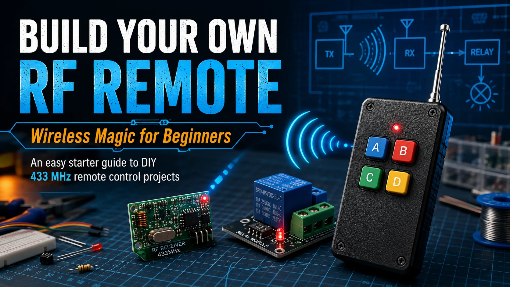
A beginner-friendly RF remote project uses a transmitter, receiver, relay module, power supply, and antenna to demonstrate how wireless control works from button press to relay click.
Reading mapArticle sections9 sections
Ever notice how a remote control feels a little like magic? Press a button, and a garage door opens. Press another, and a light turns on across the room.
The technology behind it is genuinely simple enough to understand. With a few off-the-shelf modules, you can build a working low-voltage RF remote project in an afternoon.
This guide walks through the basic chain from button press to relay click. No advanced electronics background required, but basic wiring care still matters.
RF vs Infrared
Most people first meet remote control through infrared: a TV remote or air conditioner remote. Infrared behaves like a small flashlight. The receiver needs to see the light path.
Point it the wrong way, block it with your hand, or use it from another room, and it fails.
RF remote control works through radio waves instead. The signal can pass through many non-metal obstacles, bend around furniture, and does not need line of sight.
Consumer RF remote projects often use 315MHz or 433MHz modules, depending on region and product availability. Always check local rules and buy transmitter and receiver modules that operate on the same frequency.
Three Components, One Working System
You do not need to design the RF circuit from scratch. For a beginner project, you are assembling three modules that each do one job.
- RF transmitter module: the handheld side. It sends a radio signal when the button is pressed.
- RF receiver module: the device side. It listens for the matching signal and outputs a small electrical signal.
- Relay module: the low-voltage control bridge. It lets the receiver output switch a separate load.
The chain is simple: press button, transmitter broadcasts, receiver detects the signal, receiver output triggers the relay, and the relay switches the load.
Parts List
Everything below is available from common electronics retailers. Exact part numbers vary, so check the voltage and frequency specs before connecting power.
- 433MHz transmitter module or handheld transmitter, one piece.
- 433MHz receiver module matched to the transmitter frequency, one piece.
- 5V single-channel relay module, one piece.
- 5V USB adapter, bench supply, or battery pack for the receiver side.
- Suitable battery or supply for the transmitter side, depending on the module.
- Jumper wires for low-voltage connections.
- Plastic project boxes for the transmitter and receiver side.
- A short straight antenna wire, about 17cm for 433MHz quarter-wave use.
The most common beginner mistake is buying a transmitter and receiver on different frequencies. A 315MHz transmitter will not work with a 433MHz receiver.
Wiring the Transmitter
A basic transmitter module usually has VCC, GND, DATA, and sometimes ANT pins. If you are using a finished handheld transmitter, the button and battery holder may already be built in.
Connect VCC to the module rated supply voltage and GND to ground. Do not assume every module accepts 5V. Some are 3.3V only, and powering them at 5V can damage them.
If the module expects an external button, the datasheet or seller diagram will show whether the DATA pin should be pulled high or low when pressed. Follow the module documentation rather than guessing.
Wiring the Receiver and Relay
The receiver module usually has VCC, GND, and DATA. Power it at the rated voltage, then connect DATA to the IN pin of the relay module if the logic levels are compatible.
The relay module control side has VCC, GND, and IN. VCC and GND go to the 5V supply. IN receives the trigger signal from the receiver or from a microcontroller if you add one later.
The relay switching side usually has COM, NO, and NC. For a low-voltage lamp or LED strip that turns on only when triggered, use COM and NO.
If you plan to switch 110V or 220V mains, stop and review proper electrical safety first. Use an enclosure, strain relief, fusing, correct wire gauge, proper isolation, and a relay rated for the load. If you are not trained for mains wiring, keep the project low voltage.
Testing and Troubleshooting
Power up both sides. Press the transmitter button. You should see the receiver output respond and hear the relay click.
- Frequency match: confirm transmitter and receiver are both 433MHz or both 315MHz.
- Power: measure the supply voltage at the module pins, not only at the adapter.
- Connections: check VCC, GND, DATA, relay IN, COM, and NO carefully.
- Antenna: use a straight antenna wire; do not coil it inside the box.
- Environment: test outside a metal enclosure first, because metal blocks RF.
- Logic level: some receiver outputs are not strong enough to drive a relay directly and may need a transistor or microcontroller interface.
For 433MHz, a quarter-wave antenna is roughly 17cm. A missing, shortened, coiled, or metal-shielded antenna can reduce range dramatically.
Going Further
Once the basic system works, the next step is multi-channel control. Four-channel and eight-channel transmitter and receiver sets let you control multiple outputs from one remote.
Adding a microcontroller such as an Arduino or ESP32 opens up timed switching, memory, conditional logic, and combined RF plus Wi-Fi control.
Security is the next serious topic. Basic low-cost modules are fine for lamps, buzzers, and experiments, but they should not be used as the only protection for a garage door, lock, or access-control system.
For security-sensitive applications, use a proper rolling-code system such as HCS301/KeeLoq-style architecture or a documented equivalent. EV1527 is a common learning-code family, not a rolling-code security solution.
Safety Notes Worth Reading
- Check local frequency rules before using RF equipment outdoors or at higher power.
- Use low-voltage loads for first projects.
- Never exceed the relay current rating.
- Keep mains wiring physically separated from low-voltage logic wiring.
- Use plastic or RF-transparent enclosures around antennas.
- Do not use simple fixed-code DIY modules for doors, locks, or security-critical access.
The Bigger Picture
What makes this project satisfying is that it turns wireless control from a black box into a clear chain of steps.
Button press. RF transmission. Receiver output. Relay switching. Load response.
Once you have built that chain once, every RF remote you use starts to make more sense. The same architecture scales into lighting control, greenhouse ventilation, workshop automation, gate control, and many other projects.
Start with one button and one safe low-voltage load. Learn the chain first; then make it smarter.
About the Author
Eric Huang
RF Remote Controls & Controllers Specialist
Hi, I'm Eric Huang, with 10+ years of experience in RF remote controls and controllers. I combine technical expertise with international trade knowledge to provide businesses with reliable, high-quality solutions. My goal is to ensure every client finds a trustworthy product.
Feel free to share your thoughts or ask questions. Let's connect!
Keep reading
Related articles
RF Remote Range: 10 Meters, 30 Meters, or 100 Meters?
RF remote range depends on transmitter power, modulation, antenna design, receiver sensitivity, building materials, and same-frequency interference, so open-field range and indoor range can be very different.
Read next Устранение неисправностейSame Batch of 433MHz Remotes: One Opens Instantly, One Plays Dead
When two identical 433MHz remotes behave differently on site, the fastest diagnosis starts with battery voltage under load, antenna placement, and electromagnetic interference.
Read next Динамический кодIs Your Garage Door Actually Secure? A Clear-Eyed Guide to Remote Control Cloning
Garage door remote security depends mainly on whether the system uses fixed code or rolling code. Fixed code can be copied easily; properly implemented rolling code defeats normal replay attacks.
Read nextНужна помощь сейчас?
Отправьте нам свой вопрос по совместимости, и мы ответим напрямую.
Comments
Leave a comment or RF question
Share your unstable range, batch consistency, matching, filtering, case effect, or export production question. Eric will review the details and reply directly.
Comments are handled by email for now, so you can review the message before sending.